
Toyota Sienna Service Manual: Reassembly
1. INSTALL UNDERDRIVE PLANETARY RING GEAR
HINT: Use a torque wrench with a fulcrum length of 160 mm (6.3 in.).
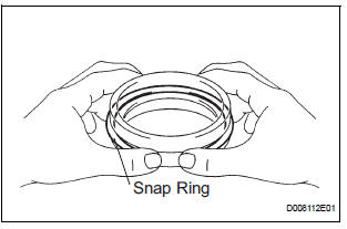
(a) Install a new snap ring to the outer race of the radial ball bearing rear.
HINT: When replacing the bearing, also replace the counter driven gear with a new one.
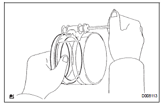
(b) Using a piston ring compressor, squeeze the snap ring.
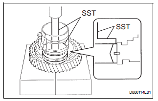
(c) Using SST and a press, press in the outer race of the radial ball bearing rear.
SST 09950-60020 (09951-00890), 09950-70010 (09951-07100)
NOTICE: Be sure not to damage the snap ring during outer race installation.
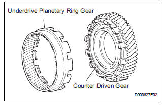
(d) Install the underdrive planetary ring gear to the counter driven gear.
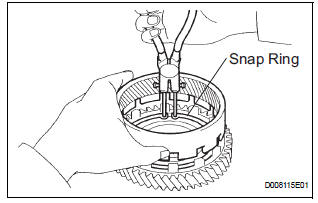
(e) Using a snap ring pliers, install the snap ring.
2. INSTALL UNDERDRIVE PLANETARY GEAR ASSEMBLY
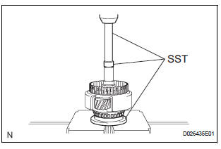
(a) Using SST and a press, press the radial ball bearing rear in the underdrive planetary gear.
SST 09502-12010, 09950-60010 (09951-00260), 09950-70010 (09951-07100)
NOTICE: Press the bearing until it becomes flat at the bottom.
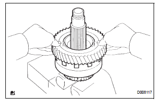
(b) Install the counter driven gear with planetary ring gear to the underdrive planetary gear.
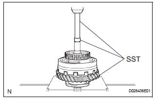
(c) Using SST and a press, press in the radial ball bearing front.
SST 09502-12010, 09950-60010 (09951-00260), 09950-70010 (09951-07100)
NOTICE: Press the counter driven gear while rotating it.
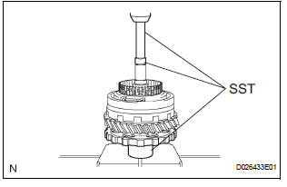
(d) Using SST and a press, press in the parking lock gear.
SST 09502-12010, 09950-60010 (09951-00260), 09950-70010 (09951-07100)
NOTICE: Press the counter driven gear while rotating it.
3. INSTALL DIFFERENTIAL DRIVE PINION
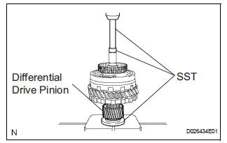
(a) Using SST and a press, press the differential drive pinion.
SST 09726-40010, 09950-60010 (09951-00260), 09950-70010 (09951-07100)
NOTICE: Press the counter driven gear while rotating it
4. INSTALL CYLINDRICAL ROLLER BEARING RACE INNER
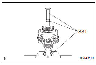
(a) Using SST and a press, press the cylindrical roller bearing race inner.
SST 09506-35010, 09950-60010 (09951-00260), 09950-70010 (09951-07100)
NOTICE: Press the counter driven gear while rotating it.
5. INSTALL FRONT PLANETARY GEAR NUT
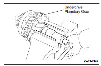
(a) Place the underdrive planetary gear in a soft jaw vise.
NOTICE: Be careful not to damage the differential drive pinion.
(b) Using a socket wrench, install a new lock nut.
Torque: 280 N*m (2,885 kgf*cm, 207 ft.*lbf)
HINT: Use a torque wrench with a fulcrum length of 750 mm (29.53 in.).
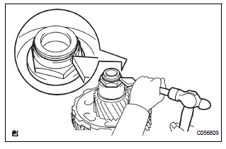
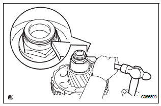
(c) Using a pin punch and hammer, stake the lock nut.
CAUTION: Be sure that there are no cracks on the nut.
6. INSPECT UNDERDRIVE PLANETARY GEAR PRELOAD
HINT: (See page AX-260)
 Inspection
1. INSPECT UNDERDRIVE PLANETARY GEAR PRELOAD
(a) Using SST, fix the underdrive planetary gear
assembly.
SST 09387-00050
(b) Using SST and a torque wrench, measure the
turning torque of th ...
Other materials:
Crankshaft position sensor
Components
Removal
1. Remove compressor and magnetic clutch
HINT:
(See page AC-227 )
2. REMOVE CRANKSHAFT POSITION SENSOR
(a) Disconnect the crankshaft position sensor
connector.
(b) Remove the bolt, and then remove the crankshaft
position sensor.
INSPECTION
1. INSPECT CRANKSHAFT ...
Starting the engine
Shift the shift lever to P and apply the brakes.
Touch the Toyota emblem side
of the electronic key to the
engine switch.
An alarm will sound to indicate that
the start function cannot detect the
electronic key that is touched to the
engine switch if any of the doors is
opened ...
Coolant Thermostat (Coolant Temperature Below Thermostat Regulating
Temperature)
HINT:
This DTC relates to the thermostat.
DESCRIPTION
This DTC is set when the Engine Coolant Temperature (ECT) does not reach 75°C
(167°F) despite
sufficient engine warm-up time.
MONITOR DESCRIPTION
The ECM estimates the ECT based on the starting temperature, engine loads,
a ...
