Toyota Sienna Service Manual: Rear evaporator temperature sensor circuit
DESCRIPTION
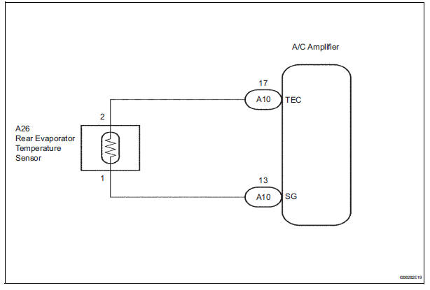
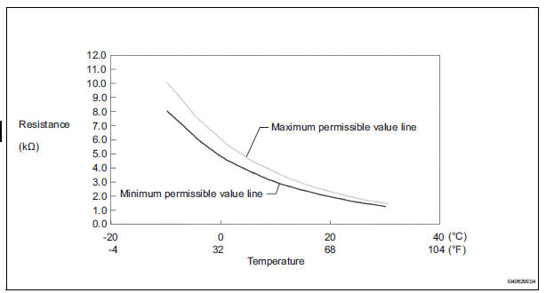
The rear evaporator temperature sensor is installed on the rear evaporator. It detects the rear evaporator temperature. The sensor sends a signal to the A/C amplifier. The resistance of the rear evaporator temperature sensor changes in accordance with the rear evaporator temperature. As the temperature decreases, the resistance increases. As the temperature increases, the resistance decreases.
The A/C amplifier applies voltage (5 V) to the rear evaporator temperature
sensor and reads voltage
changes as the resistance of the rear evaporator temperature sensor changes.
WIRING DIAGRAM
INSPECTION PROCEDURE
1 READ VALUE OF INTELLIGENT TESTER
(a) Connect the intelligent tester to the DLC3.
(b) Turn the ignition switch to the ON position and turn the intelligent tester main switch on.
(c) Select the item below in the DATA LIST, and read the display on the intelligent tester.
DATA LIST / AIR CONDITIONER: 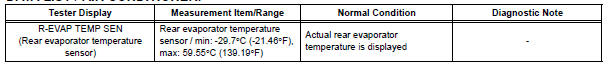
OK: The display is as specified in the normal condition column.
Result 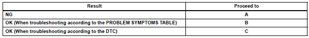

2 INSPECT REAR EVAPORATOR TEMPERATURE SENSOR
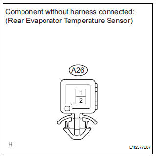
(a) Remove the rear evaporator temperature sensor.
(b) Measure the resistance according to the value(s) in the table below.
Standard resistance 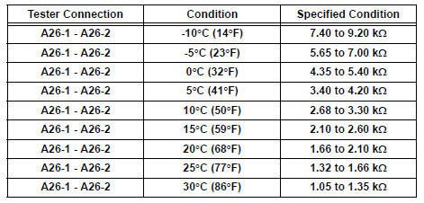
NOTICE:
- Even slightly touching the sensor may change the resistance value. Be sure to hold the connector of the sensor.
- When measuring, the sensor temperature must be the same as the rear evaporator temperature.
HINT: As the temperature increases, the resistance decreases (see the graph).

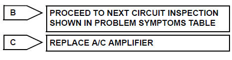
3 CHECK HARNESS AND CONNECTOR (REAR EVAPORATOR TEMPERATURE SENSOR - A/C AMPLIFIER)
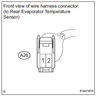
(a) Disconnect the rear evaporator temperature sensor connector.
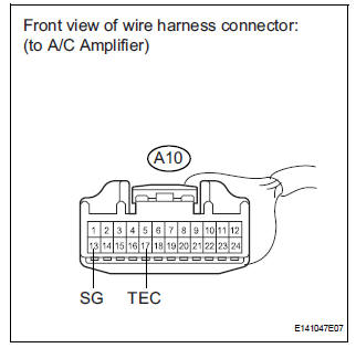
(b) Disconnect the A/C amplifier connector.
(c) Measure the resistance according to the value(s) in the table below.
Standard resistance 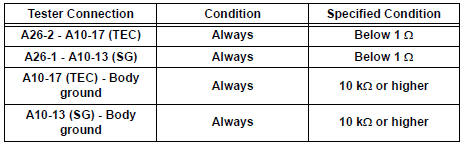

REPLACE A/C AMPLIFIER
 Evaporator temperature sensor circuit
DESCRIPTION
The evaporator temperature sensor (A/C thermistor) is installed on the
evaporator in the air conditioning
unit. It detects the temperature of the cooled air that has passed through the ...
 Rear Room Temperature Sensor Circuit
DESCRIPTION
This sensor detects the rear cabin temperature that is used as the basis for
temperature control and
sends a signal to the A/C amplifier.
WIRING DIAGRAM
INSPECTION PROCEDURE
1 R ...
Other materials:
Cooling fan relay
On-vehicle inspection
1. Cooling fan relay
(a) Remove the relay from engine room relay block No.
1.
(b) Measure the resistance of the relay.
Standard resistance
If the result is not as specified, replace the cooling
fan relay.
(c) Install the relay to engine room relay block No. ...
Side Airbag Sensor Assembly RH Circuit Malfunction
DTC B1140/32 Side Airbag Sensor Assembly RH Circuit Malfunction
DESCRIPTION
The side airbag sensor RH circuit consists of the center airbag sensor
assembly and side airbag sensor
RH.
If the center airbag sensor assembly receives signals from the side airbag
sensor RH, it judges whether or
...
Transmission Error
DTC 01-DC Transmission Error
DESCRIPTION
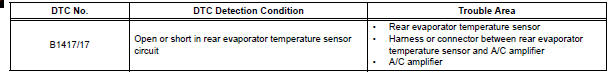
DTC No.
DTC Detection Condition
Trouble Area
01-DC
*1
Transmission to component shown by sub-code failed.
(Detecting this DTC does not always mean actual
failure.)
If the same sub-code is recorded in other ...
