Toyota Sienna Service Manual: Refrigerant
On-vehicle inspection
1. INSPECT REFRIGERANT PRESSURE WITH MANIFOLD GAUGE SET
(a) This method uses a manifold gauge set to locate problem areas. Read the manifold gauge pressure when these conditions are established.
Test conditions:
- Temperature at the air inlet is 30 to 35°C (86 to 95°F).
- Engine is running at 1,500 rpm.
- All doors are fully open.
- Blower speed control switch is at HI.
- Temperature control switch is at MAX. COOL.
- A/C switch is ON.
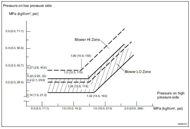
(b) Gauge readings (Reference)
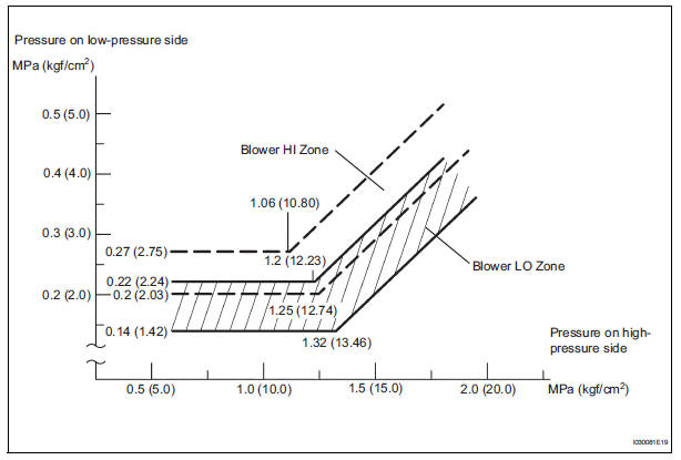
(1) Normally functioning refrigeration system
Gauge reading 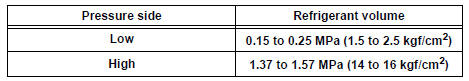
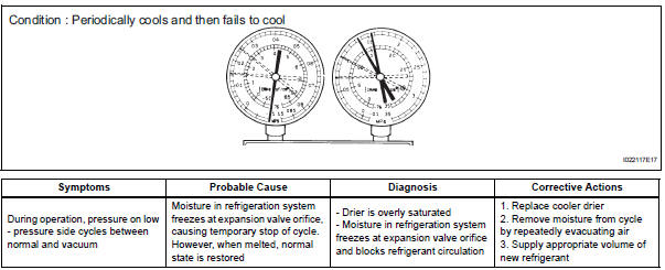
(2) The A/C system periodically changes between normal and improper function due to moisture in the refrigerant system.
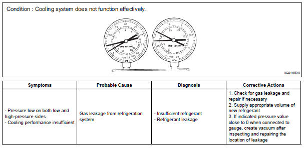
(3) The A/C system does not function effectively due to insufficient cooling.
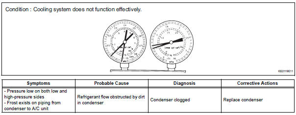
(4) The A/C system does not function effectively due to poor circulation of the refrigerant.
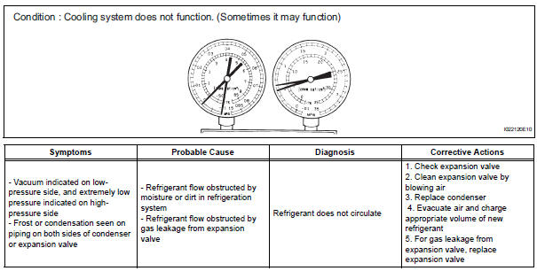
(5) The A/C system does not function intermittently because the refrigerant does not circulate.
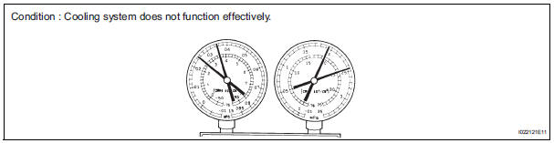
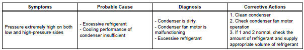
(6) The A/C system does not function effectively due to overcharged refrigerant or insufficient cooling of the condenser.
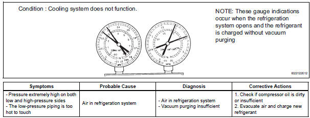
(7) The A/C system does not function due to air in the refrigeration system.
| CAUTION: The low-pressure piping may be very hot and cause serious burns. |
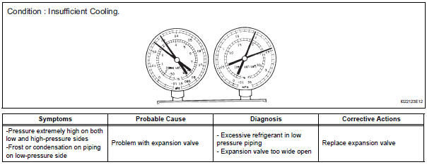
(8) The A/C system does not function effectively due to an expansion valve malfunction.
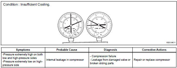
(9) The A/C system does not function due to a defective compressor.
Gauge readings (Reference)
 Terminals of ecu
1. A/C AMPLIFIER
HINT:
Check from the rear of the connector while it is
connected to the A/C amplifier.
(a) Waveform 1:
(b) Waveform 2: ...
 Replacement
1. DISCHARGE REFRIGERANT FROM
REFRIGERATION SYSTEM
SST 07110-58060 (07117-58080, 07117-58090,
07117-78050, 07117-88060, 07117-88070,
07117-88080)
(a) Turn the A/C switch to ON.
(b) Operating t ...
Other materials:
Actuator Supply Voltage Circuit / Open
DESCRIPTION
The ECM monitors the output voltage to the throttle actuator. This self-check
ensures that the ECM is
functioning properly. The output voltage is usually 0 V when the ignition switch
is turned off. If the output
voltage is higher than 7 volts when the ignition switch is turned ...
Drive belt
COMPONENTS
REMOVAL
1. REMOVE FRONT WHEEL RH
2. REMOVE FRONT FENDER APRON SEAL RH (See
page EM-26)
3. REMOVE V-RIBBED BELT
(a) Using SST, release the belt tension by turning the
belt tensioner counterclockwise, and remove the Vribbed
belt from the belt tensioner.
SST 09249-63010
(b) ...
Installation
HINT:
Install the RH side by the same procedure as the LH side.
1. INSTALL FRONT DISC BRAKE CYLINDER SLIDE BUSH
(a) Apply the lithium soap base glycol grease to a new
front disc brake cylinder slide bush.
(b) Install the cylinder slide bush to the bottom side of
the front disc brake cyli ...
