Toyota Sienna Service Manual: Installation
HINT: Install the RH side by the same procedure as the LH side.
1. INSTALL FRONT DISC BRAKE CYLINDER SLIDE BUSH
(a) Apply the lithium soap base glycol grease to a new front disc brake cylinder slide bush.
(b) Install the cylinder slide bush to the bottom side of the front disc brake cylinder slide pin (No. 2).
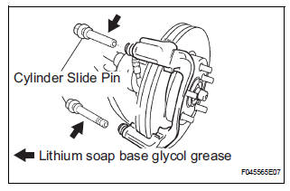
2. INSTALL FRONT DISC BRAKE CYLINDER SLIDE PIN
(a) Apply the lithium soap base glycol grease to the sliding part and the sealing surface of the front disc brake cylinder slide pin (No. 1) and front disc brake cylinder slide pin (No. 2).
(b) Install the front disc brake cylinder slide pin (No. 1) and front disc brake cylinder slide pin (No. 2) to the front disc brake cylinder mounting LH.
(c) Install the front disc brake cylinder slide pin (No. 2) to the front disc brake cylinder mounting LH.
3. INSTALL FRONT DISC BRAKE CYLINDER MOUNTING LH
(a) Install the front disc brake cylinder mounting with the 2 bolts.
Torque: 107 N*m (1,090 kgf*cm, 79 ft.*lbf)
4. INSTALL FRONT DISC BRAKE PAD SUPPORT PLATE
(a) Install the front disc brake pad support plate (No. 1) and front disc brake pad support plate (No. 2) to the front disc brake cylinder mounting LH.
5. INSTALL ANTI SQUEAL SHIM KIT FRONT
NOTICE: If necessary, replace the anti squeal shim kit when replacing the brake pad.
(a) Apply disc brake grease to each anti squeal shim.
(b) Install anti squeal shims on each pad.
(c) Install the pad wear indicator plate facing upward, and install each pad.
6. INSTALL DISC BRAKE PAD KIT FRONT (PAD ONLY)
(a) Install the disc brake pad kit front to the front disc brake cylinder mounting LH.
NOTICE: There should be no oil or grease on the friction surfaces of the pads and the disc.
7. REMOVE FRONT DISC BRAKE CYLINDER ASSEMBLY LH
(a) Install the front disc brake cylinder sub-assembly with the 2 bolts.
Torque: 34 N*m (350 kgf*cm, 25 ft.*lbf) (b) Install a 2 new gaskets and flexible hose with the union bolt.
Torque: 29 N*m (296 kgf*cm, 21 ft.*lbf)
HINT: Install the flexible hose lock securely in the lock hole in the disc brake cylinder.
8. FILL RESERVOIR WITH BRAKE FLUID (See page BR- 3)
9. BLEED BRAKE MASTER CYLINDER (See page BR-3)
10. BLEED BRAKE LINE (See page BR-4)
11. BLEED BRAKE ACTUATOR (w/ VSC) (See page BR- 4)
12. CHECK FLUID LEVEL IN RESERVOIR (See page BR- 7)
13. CHECK BRAKE FLUID LEAKAGE
14. INSTALL FRONT WHEEL Torque: 103 N*m (1,050 kgf*cm, 76 ft.*lbf)
 Reassembly
1. INSTALL FRONT DISC
(a) Aligning the matchmarks, install the front disc.
HINT:
Select the installation position where the disc has
the minimum runout.
2. INSPECT DISC RUNOUT
(a) Temporaril ...
 Rear disc brake
COMPONENTS
...
Other materials:
Diagnostic trouble code chart
HINT:
The parameters listed in the chart may not confirm exactly to
those read during the DTC check due to the type of
instrument or other factors.
If a trouble code is displayed during the DTC check in the
check mode, check the circuit for the code listed in the table
below. For details of ...
How to proceed with
troubleshooting
HINT:
Use this procedure to troubleshoot the engine immobiliser
system.
The intelligent tester should be used in steps 4, 5 and 7.
1 VEHICLE BROUGHT TO WORKSHOP
2 CUSTOMER PROBLEM ANALYSIS CHECK AND SYMPTOM CHECK
3 CRANK ENGINE FOR MORE THAN 10 SECONDS
4 CHECK FOR DTC
C ...
Installation
1. INSTALL 3 POINT TYPE NO. 2 REAR SEAT BELT ASSEMBLY
Check the degree of tilt when the belt begins to lock
the ELR.
Check that the belt does not lock within 15 of
tilt in all directions but that the belt locks with
over 45 of tilt, when gently moving the
retractor.
If ...
