Toyota Sienna Service Manual: Replacement
1. DISCHARGE REFRIGERANT FROM REFRIGERATION SYSTEM
SST 07110-58060 (07117-58080, 07117-58090, 07117-78050, 07117-88060, 07117-88070, 07117-88080)
(a) Turn the A/C switch to ON.
(b) Operating the cooler compressor at the engine rpm of approx. 1,000 for 5 to 6 minutes, circulate the refrigerant and collect the compressor oil remaining in each component into the cooler compressor as much as possible.
(c) Stop the engine.
(d) Let the refrigerant gas out.
SST 07110-58060 (07117-58080, 07117-78050, 07117-88060, 07117-88070, 07117-88080)
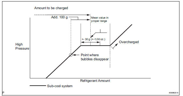
2. CHARGE REFRIGERANT
(a) Using a vacuum pump, perform a vacuum purging.
(b) Charge refrigerant, HFC-134a (R134a).
Standard: 780 +- 30 g (27.5 +- 1.06 oz.) SST 07110-58060 (07117-58060, 07117-58070, 07117-58080, 07117-58090, 07117-78050, 07117-88060, 07117-88070, 07117-88080)
3. WARM UP ENGINE
4. INSPECT REFRIGERANT LEAK
(a) Using a gas leak detector, check for leakage of the refrigerant.
Refrigerant line
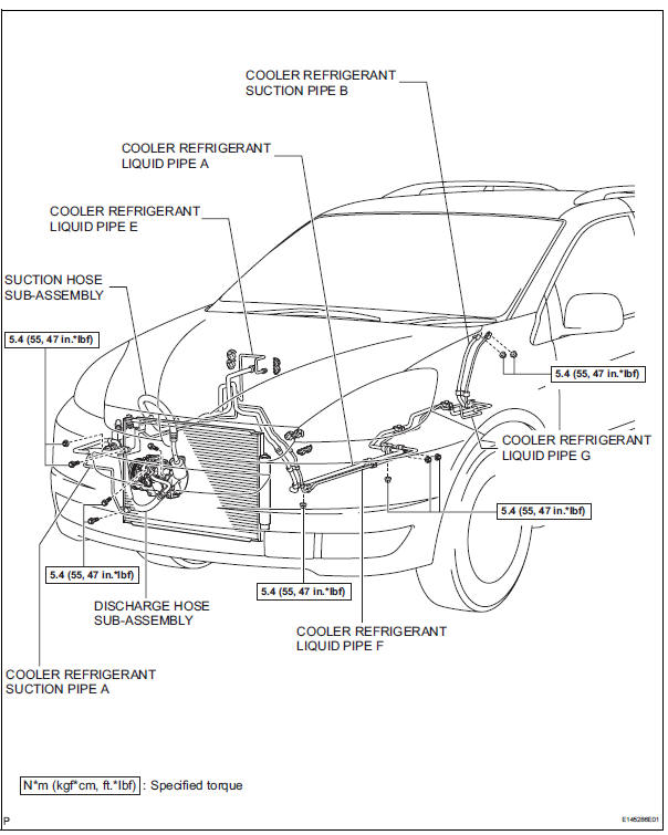
COMPONENTS
 Refrigerant
On-vehicle inspection
1. INSPECT REFRIGERANT PRESSURE WITH MANIFOLD GAUGE SET
(a) This method uses a manifold gauge set to locate
problem areas. Read the manifold gauge pressure
when these conditi ...
 Air conditioning unit
COMPONENTS
...
Other materials:
Power Source Circuit
DESCRIPTION
Power is supplied to the fold seat control ECU through the L-RR2 SEAT and
R-RR2 SEAT fuses.
WIRING DIAGRAM
INSPECTION PROCEDURE
1 INSPECT FUSE (L-RR2 SEAT, R-RR2 SEAT)
Remove the fuses from the R/B No. 3.
Measure the resistance according to the value(s) in the
...
Sound Signal Circuit between Radio Receiver and Television Display
Assembly
DESCRIPTION
The television display assembly sends a sound signal to the radio receiver
through this circuit.
The sound signal that has been sent is amplified by the stereo component
amplifier or radio receiver
(built-in amplifier), and then is sent to the speakers.
If there is an open or ...
Inspection
1. INSPECT RUNOUT OF DIFFERENTIAL RING GEAR
(a) Using a dial gauge , check the runout of the ring
gear.
Maximum runout:
0.07 mm (0.0028 in.)
If the runout is greater than the maximum, replace
the ring gear with a new one.
2. INSPECT DIFFERENTIAL RING GEAR BACKLASH
(a) Using a dial gauge, ...
