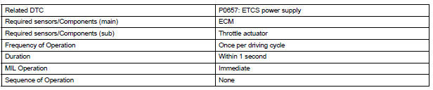
Toyota Sienna Service Manual: Actuator Supply Voltage Circuit / Open

DESCRIPTION
The ECM monitors the output voltage to the throttle actuator. This self-check ensures that the ECM is functioning properly. The output voltage is usually 0 V when the ignition switch is turned off. If the output voltage is higher than 7 volts when the ignition switch is turned off, the ECM will illuminate the MIL and set a DTC when the ignition switch is turned on.

MONITOR STRATEGY
TYPICAL ENABLING CONDITIONS

TYPICAL MALFUNCTION THRESHOLDS

INSPECTION PROCEDURE
1 CHECK WHETHER DTC OUTPUT RECURS (IN ADDITION TO DTC P0657)
(a) Connect the intelligent tester to the DLC3.
(b) Turn the ignition switch to the ON position.
(c) Turn the tester on.
(d) Clear the DTC.
(e) Turn the ignition switch off.
(f) Disconnect the battery negative terminal and wait for 1 minute.
(g) Connect the battery negative terminal.
(h) Turn the ignition switch to the ON position for 10 seconds.
(i) Turn the ignition switch off.
(j) Turn the ignition switch to the ON position.
(k) Enter the following menus: DIAGNOSIS / ENHANCED II / DTC INFO / CURRENT CODES.
(l) Read the DTCs.
Result 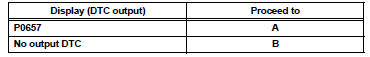

REPLACE ECM
 VIN not Programmed or Mismatch - ECM / PCM
DESCRIPTION
DTC P0630 is set when the Vehicle Identification Number (VIN) is not stored
in the Engine Control Module
(ECM) or the input VIN is not accurate. Input the VIN with the intelligent ...
 Transmission Range Sensor Circuit Malfunction (PRNDL Input)
DESCRIPTION
The park/neutral position switch detects the shift lever position and sends
signals to the ECM.
HINT:
After confirming DTC P0705, use the intelligent tester to confirm the PN ...
Other materials:
Removal
NOTICE:
Do not adjust the brake booster push rod.
Do not change the combination of the diameter
converting unit and brake.
1. REMOVE FRONT WHEEL
2. DRAIN BRAKE FLUID
NOTICE:
Wash the brake fluid off immediately if it attaches to
any painted surfaces.
3. SEPARATE BATTERY NEGATIVE TERM ...
Short to GND in Front Pretensioner Squib RH
Circuit
DTC B0132/61 Short to GND in Front Pretensioner Squib RH
Circuit
DESCRIPTION
The front pretensioner squib RH circuit consists of the center airbag sensor
assembly and the front seat
outer belt assembly RH.
This circuit instructs the SRS to deploy when deployment conditions are met.
DTC B ...
Problem symptoms table
HINT:
Use the table below to help determine the cause of the
problem symptoms. The potential causes of the symptoms
are listed in order of probability in the ''Suspected Area''
column of the table. Check each symptom by checking the
suspected areas in the order they are listed. Rep ...
