Toyota Sienna Service Manual: Engine Coolant Temperature Receiver Gauge Malfunction
DESCRIPTION
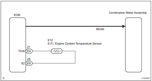
The meter CPU receives engine coolant temperature signals from the ECM via the multiplex communication lines. The meter CPU displays engine coolant temperature that is calculated based on the data received from the ECM.
WIRING DIAGRAM
INSPECTION PROCEDURE
HINT: If there is an open or short in the engine coolant temperature sensor circuit, the ECM will store the DTCs.
Perform troubleshooting of the "SFI System"
1 CHECK MULTIPLEX COMMUNICATION SYSTEM
- Check if the MULTIPLEX communication DTC is output
Result

2 PERFORM ACTIVE TEST BY INTELLIGENT TESTER
- Connect the intelligent tester to the DLC3.
- Turn the ignition switch to the ON position.
- Turn the tester ON.
- Enter the following menus: DIAGNOSIS / OBD/MOBD / METER / ACTIVE TEST.
- Check the operation by referring to the values in the table below.
METER:

OK: Needle indication is normal.
3 READ VALUE OF INTELLIGENT TESTER
- Connect the intelligent tester to the DLC3.
- Turn the ignition switch to the ON position.
- Turn the tester ON.
- Enter the following menus: DIAGNOSIS / ENGINE / DATA LIST.
- Check the values by referring to the values in the table below.
ENGINE:

4 REPLACE COMBINATION METER ASSEMBLY
OK: The operation of the combination meter assembly returns to normal.
END
 Fuel Receiver Gauge Malfunction
DESCRIPTION
The meter CPU uses the fuel sender gauge assembly to determine the level of
the fuel in the fuel tank.
The resistance of the fuel sender gauge will vary between approximately 15 ] ...
 Driver Side Seat Belt Warning Light does not Operate
DESCRIPTION
When turning the ignition switch to the ON position, the combination meter
assembly communicates with
the supplemental restraint system by the multiplex communication system. Unless
...
Other materials:
Identification information
VEHICLE IDENTIFICATION AND SERIAL NUMBERS
1. VEHICLE IDENTIFICATION NUMBER
(a) The vehicle identification number is stamped on the
vehicle identification number plate and the
certification label, as shown in the illustration.
A:
Vehicle Identification Number Plate
B:
...
AVC-LAN Circuit
DESCRIPTION
Each unit of the navigation system connected to the AVC-LAN (communication
bus) transfers the signal of
each switch by communication.
When a short to +B or short to ground occurs in this AVC-LAN, the navigation
system will not function
normally as the communication is discontin ...
Brake Switch "A" Circuit
DTC P0571 Brake Switch "A" Circuit
DESCRIPTION
When the brake pedal is depressed, the stop light switch sends a signal to
the ECM. When the ECM
receives this signal, it cancels the cruise control. The fail-safe function
operates to enable normal driving
even if there is a malfuncti ...
