Toyota Sienna Service Manual: Inspection
1. INSPECT MAGNETIC CLUTCH CLEARANCE
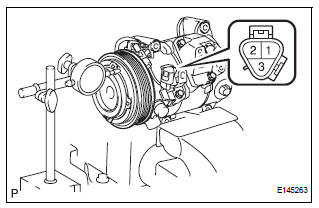
(a) Set the dial indicator to the magnetic clutch hub.
(b) Connect the battery positive lead to the terminal 1 of the magnet clutch connector and the negative lead to the earth wire. Turn on and off the magnetic clutch and measure the clearance.
Standard clearance: 0.35 to 0.60 mm (0.013 to 0.023 in.)
If the measured value is not within the standard range, remove the magnetic clutch hub and adjust it with the magnetic clutch washers.
NOTICE: Adjustment can be performed with 3 or less magnetic clutch washers.
2. INSPECT COMPRESSOR OIL
(a) When replacing the compressor and magnetic clutch with a new one, after gradually removing the refrigerant gas from the service valve, drain the following amount of oil from the new compressor and magnetic clutch before installation.
Standard: (Oil capacity inside new compressor and magnetic clutch: 225 + 15 cc (7.6 + 0.5 fl.oz.)) - (Remaining oil amount in the removed compressor and magnetic clutch) = (Oil amount to be removed when replacing)
NOTICE:
- When checking the compressor oil level, observe the precautions on the cooler removal / installation.
- Because compressor oil remains in the pipes of the vehicle, if a new compressor and magnetic clutch is installed without removing some oil inside, the oil amount becomes excessive, preventing heat exchange in the refrigerant cycle and causing refrigerant failure.
- If the remaining oil in the removed compressor and magnetic clutch is too small in volume, check for oil leakage.
- Be sure to use ND-OIL 8 for compressor oil.
3. INSPECT COMPRESSOR AND MAGNETIC CLUTCH
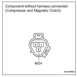
(a) Disconnect the connector from the compressor and magnetic clutch.

(b) Disconnect the connector from the magnetic clutch.
(c) Measure the resistance according to the value(s) in the table below.
Standard resistance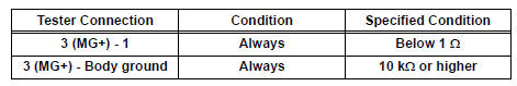
If the resistance is not as specified, replace the compressor and magnetic clutch.
4. INSPECT MAGNETIC CLUTCH
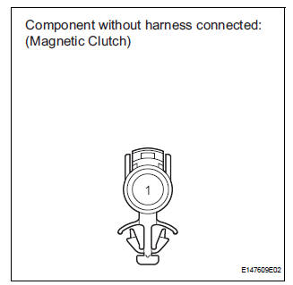
(a) Measure the resistance according to the value(s) in the table below.
Standard resistance 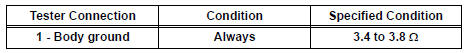
(b) When connector terminal A1 is connected to the positive (+) battery terminal, check that the following occurs: 1) the magnetic clutch's operating sound can be heard, and 2) the magnetic clutch's hub and rotor lock.
If the result is not as specified, replace the magnetic clutch.
 Disassembly
1. REMOVE MAGNETIC CLUTCH ASSEMBLY
(a) Place the compressor and magnetic clutch in a vise.
(b) Using locking pliers, hold the magnetic clutch hub.
(c) Remove the bolt, magnetic clutch hub, and
...
 Reassembly
1. INSTALL MAGNETIC CLUTCH ASSEMBLY
(a) Install the magnetic clutch stator while aligning the
protrusion on the stator with the notch on the air
compressor assembly as shown in the illustration ...
Other materials:
Check mode procedure
HINT:
Check mode has a higher sensitivity to malfunctions and can
detect malfunction that normal mode cannot detect. Check
mode can also detect all the malfunctions that normal mode
can detect. In check mode, DTCs are detected with 1-trip
detection logic.
Dtc check (check mode)
HINT:
I ...
Disassembly
1. REMOVE REAR SEAT LEG COVER LH
Remove the 2 screws and seat leg cover.
2. REMOVE REAR SEAT LEG COVER RH
Remove the 2 screws and seat leg cover.
3. REMOVE REAR SEAT LEG SIDE COVER LH
Remove the 2 screws and leg side cover.
4. REMOVE LH SEAT REAR SEAT LOCK COVE ...
Disposal
HINT:
When scrapping a vehicle equipped with the SRS or
disposing of the front passenger airbag assembly, be sure to
deploy the airbag first in accordance with the procedure
described below. If any abnormality occurs with airbag
deployment, contact the SERVICE DEPT. of the TOYOTA
MOTOR SALES, ...
