Toyota Sienna Service Manual: Removal
1. REMOVE REAR WHEEL
2. REMOVE EXHAUST PIPE ASSEMBLY
HINT: Perform this procedure only when removing the RH side.
(See page EX-8)
3. REMOVE REAR SPEED SENSOR LH
HINT: (See page DS-21)
4. REMOVE REAR AXLE SHAFT NUT LH
HINT: (See page DS-21)
5. REMOVE REAR DRIVE SHAFT ASSEMBLY LH
HINT: (See page DS-21)
6. REMOVE REAR DIFFERENTIAL SIDE GEAR SHAFT BOLT
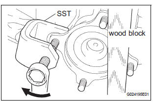
(a) Using SST and wood block, remove the rear differential side gear shaft bolt.
SST 09611-12010

 Installation
1. INSTALL REAR DIFFERENTIAL SIDE GEAR SHAFT BOLT
(a) Install the bolt tightening the nut through the plate
washer.
2. INSTALL REAR DRIVE SHAFT ASSEMBLY LH
HINT:
(See page DS-26)
3. INSTALL ...
Other materials:
Catalyst System Efficiency Below Threshold
DTC P0420 Catalyst System Efficiency Below Threshold
(Bank 1)
DTC P0430 Catalyst System Efficiency Below Threshold
(Bank 2)
MONITOR DESCRIPTION
The ECM uses the sensors mounted in front of and behind the three-way
catalyst (TWC) to monitor its
efficiency. The first sensor, an Air Fuel ratio ...
Television Display Assembly Communication Error
INSPECTION PROCEDURE
1 IDENTIFY THE COMPONENT SHOWN BY THE SUB-CODE
Enter the diagnostic mode.
Press the "LAN Mon" switch to change to "LAN Monitor"
mode.
Identify the component shown by the sub-code.
HINT:
"110 (multi-display)" i ...
Removal
1. DRAIN BRAKE FLUID
NOTICE:
Wash brake fluid off immediately if it adheres to any
painted surface.
2. DISCONNECT BATTERY NEGATIVE TERMINAL
3. REMOVE AIR CLEANER ASSEMBLY WITH HOSE
4. REMOVE BRAKE ACTUATOR WITH BRACKET
(a) Release the latch of the brake actuator connector to
disconnect the c ...
