Toyota Sienna Service Manual: Removal
HINT: Replace the RH side by the same procedures as the LH side.
1. REMOVE REAR WHEEL
2. REMOVE REAR DISC BRAKE CALIPER ASSEMBLY LH
(a) Removing the 2 bolts, separate the rear disc brake caliper assembly LH for disc rear brake type.
NOTICE: Using a string and so on, hang down the disc brake caliper.
3. REMOVE REAR DISC
(a) Remove rear disc for disc rear brake type.
4. REMOVE REAR BRAKE DRUM SUB-ASSEMBLY
(a) Remove rear brake drum sub-assembly for drum rear brake type.
5. SEPARATE SKID CONTROL SENSOR WIRE
(a) Disconnect the connector
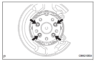
6. REMOVE REAR AXLE HUB & BEARING ASSEMBLY LH

(a) Remove the 4 bolts and hub & bearing assembly LH.
 On-vehicle inspection
1. INSPECT REAR AXLE HUB BEARING BACKLASH
(a) Using a dial gauge, check for backlash near the
center of the axle hub.
Maximum:
0.05 mm (0.0020 in.)
If backlash exceeds the maximum, replace th ...
 Installation
1. INSTALL REAR AXLE HUB & BEARING ASSEMBLY LH
(a) Install the hub & Bearing assembly LH with the 4
bolts.
Torque: 56 N*m (571 kgf*cm, 41 ft.*lbf)
2. INSPECT BEARING BACKLASH (See page ...
Other materials:
Occupant Classification System Malfunction
DTC B1150/23 Occupant Classification System Malfunction
DESCRIPTION
The occupant classification system circuit consists of the center airbag
sensor assembly and the occupant
classification ECU.
If the center airbag sensor assembly receives signals from the occupant
classification ECU, it d ...
Open in Stop Light Switch Circuit
DTC C1249/49 Open in Stop Light Switch Circuit
DESCRIPTION
WIRING DIAGRAM
INSPECTION PROCEDURE
1 CHECK STOP LIGHT SWITCH OPERATION
(a) Check that the stop light comes on when the brake pedal
is depressed and goes off when the brake pedal is
released.
OK
HINT:
Check the stop li ...
Open in Occupant Classification ECU Battery
Positive Line
DTC B1794 Open in Occupant Classification ECU Battery
Positive Line
DESCRIPTION
This circuit consists of the occupant classification ECU and the power source
circuit (battery, fuse, wire
harness).
DTC B1794 is recorded when a malfunction is detected in the occupant
classification ECU or t ...
