
Toyota Sienna Service Manual: VIN not Programmed or Mismatch - ECM / PCM
DTC P0630 VIN not Programmed or Mismatch - ECM / PCM
DESCRIPTION
DTC P0630 is set when the Vehicle Identification Number (VIN) is not stored in the Engine Control Module (ECM) or the input VIN is not accurate. Input the VIN with the intelligent tester.

MONITOR STRATEGY
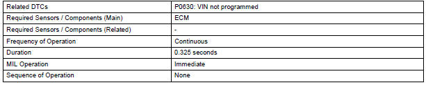
TYPICAL ENABLING CONDITIONS

TYPICAL MALFUNCTION THRESHOLDS

COMPONENT OPERATING RANGE

INSPECTION PROCEDURE
1 READ CURRENT DTC
- Connect the intelligent tester to the DLC3.
- Turn the ignition switch to the ON position and turn the tester on.
- Select the following menu items: DIAGNOSIS / ENHANCED OBD II / DTC INFO / CURRENT CODES.
- Read the DTCs.
Result

If any DTCs other than P0630 are output, troubleshoot those DTCs first.
NOTICE: If P0630 is set, the VIN must be input to the ECM using the intelligent tester. However, all DTCs are cleared automatically by the tester when inputting the VIN. If DTCs other than P0630 are set, check them first.
2 INPUT VIN WITH INTELLIGENT TESTER
HINT: Refer to "REGISTRATION"
3 READ CURRENT DTC
- Connect the intelligent tester to the DLC3.
- Turn the ignition switch to the ON position and turn the tester on.
- Select the following menu items: DIAGNOSIS / ENHANCED OBD II / DTC INFO / CURRENT CODES.
- Read the DTCs again.
Result: DTC is not output (P0630).
END
 Starter Relay Circuit High
DTC P0617 Starter Relay Circuit High
MONITOR DESCRIPTION
While the engine is being cranked, the positive battery voltage is applied to
terminal STA of the ECM.
If the ECM detects the Starter Co ...
 Actuator Supply Voltage Circuit / Open
DTC P0657 Actuator Supply Voltage Circuit / Open
DESCRIPTION
The ECM monitors the output voltage to the throttle actuator. This self-check
ensures that the ECM is
functioning properly. The output ...
Other materials:
Installation
HINT:
Use the same procedures for the RH side and LH side.
The procedures listed below are for the LH side.
1. INSTALL REAR AIRBAG SENSOR LH
Check that the ignition switch is off.
Check that the battery negative (-) terminal is
disconnected.
CAUTION:
...
Operating instructions
Turning the end of the lever turns on the lights as follows:
The illustration is intended as an example.
U.S.A.
Canada
The headlights, side marker,
parking lights, daytime running
lights (if equipped) and so on turn on and off
automatically (when the engine switch is ...
No. 2 Speaker with box
COMPONENTS
ON-VEHICLE INSPECTION
1. INSPECT NO.2 SPEAKER WITH BOX
HINT:
Remove interior parts so that the No.2 speaker with box
can be seen.
Check the speaker installation.
OK:
The speaker is securely installed.
If the result is not as specified, reinstall the No.2
s ...
