Toyota Sienna Service Manual: Removal
1. REMOVE FRONT WHEEL
2. REMOVE FRONT AXLE HUB LH NUT
HINT: (See page AH-4) SST 09930-00010
3. SEPARATE SPEED SENSOR FRONT LH
HINT: (See page AH-4)
4. SEPARATE FRONT DISC BRAKE CALIPER ASSEMBLY LH
HINT: (See page AH-4)
5. REMOVE FRONT DISC
6. SEPARATE TIE ROD ASSEMBLY LH
HINT: (See page AH-4) SST 09628-62011
7. SEPARATE FRONT SUSPENSION ARM SUBASSEMBLY LOWER NO.1 LH
HINT: (See page AH-4)
8. REMOVE FRONT AXLE ASSEMBLY LH
HINT: (See page AH-4)
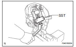
9. REMOVE LOWER BALL JOINT ASSEMBLY FRONT LH
a) Remove the cotter pin and nut.
(b) Using SST, remove the lower ball joint assembly front LH.
SST 09628-62011
 Front lower ball joint
COMPONENTS
...
 Inspection
1. INSPECT LOWER BALL JOINT ASSEMBLY FRONT LH
(a) As shown in the illustration, flip the ball joint stud
back and forth 5 times, before installing the nut.
(b) Using a torque wrench, turn the ...
Other materials:
Installation
1. INSTALL REAR AXLE BEAM DAMPER
(a) Install the rear axle beam damper to the rear axle
beam assembly.
2. INSTALL REAR AXLE CARRIER BUSH LH
(a) Align the matchmarks on the axle beam assembly
with the 2 notches of a new bushing and temporarily
install the bushing to the rear axle beam assem ...
Adjustment
1. VEHICLE PREPARATION FOR FOG LIGHT AIMING
Prepare the vehicle:
Ensure there is no damage or deformation to the
body around the fog lights.
Fill the fuel tank.
Make sure that the oil is filled to the specified
level.
Make sure that the coolant is fi ...
How to proceed with
troubleshooting
1 VEHICLE BROUGHT TO WORKSHOP
2 INSPECT BATTERY VOLTAGE
Standard voltage:
11 to 14 V
If the voltage is below 11 V, recharge or replace the battery
before proceeding.
3 BASIC INSPECTION
Turn the ignition switch ON.
Check whether or not the radio receiver turns on.
Result
4 CHE ...
