Toyota Sienna Service Manual: Air Conditioning Compressor Magnetic Clutch Circuit
DESCRIPTION
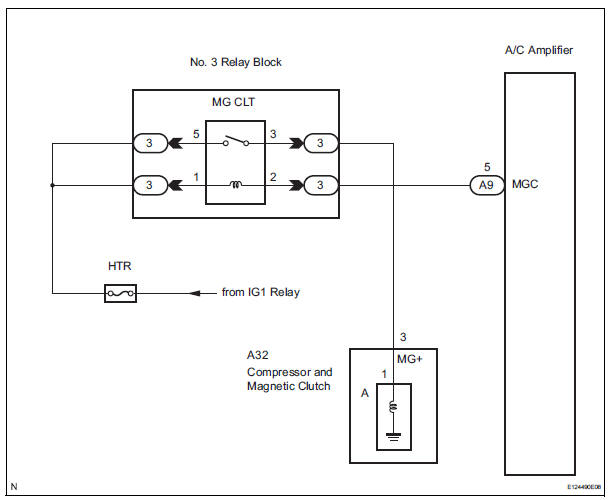
When the A/C amplifier is turned on, a magnetic clutch ON signal is sent from the MGC terminal of the A/ C amplifier. Then, the MG CLT relay turns on to operate the magnetic clutch.
WIRING DIAGRAM
INSPECTION PROCEDURE
1 CHECK CAN COMMUNICATION SYSTEM
(a) Use the intelligent tester to check if the CAN communication system is functioning normally.
Result 

2 CHECK MULTIPLEX COMMUNICATION SYSTEM
(a) Use the intelligent tester to check if the multiplex communication system is functioning normally.
Result 

3 PERFORM ACTIVE TEST BY INTELLIGENT TESTER
(a) Connect the intelligent tester to the DLC3.
(b) Turn the ignition switch to the ON position and turn the intelligent tester main switch on.
(c) Select the item below in the ACTIVE TEST and then check that the relay operates.
ACTIVE TEST / AIR CONDITIONER:
OK: Magnetic clutch relay operates.


PROCEED TO NEXT CIRCUIT INSPECTION SHOWN IN PROBLEM SYMPTOMS TABLE
4 INSPECT FUSE (HTR)
(a) Remove the HTR fuse from the driver side junction block.
(b) Measure the resistance according to the value(s) in the table below.
Standard resistance 
(c) Reconnect the HTR fuse to the driver side junction block.

5 INSPECT RELAY (MG CLT)
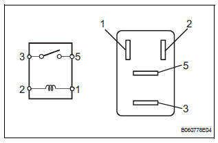
(a) Remove the MG CLT relay from the No. 3 relay block.
(b) Measure the resistance according to the value(s) in the table below.
Standard resistance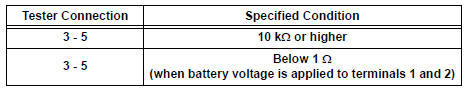
(c) Install the MG CLT relay to the No. 3 relay block.

6 CHECK HARNESS AND CONNECTOR (A/C AMPLIFIER - BATTERY)
(a) Disconnect the connector from the A/C amplifier.
(b) Measure the voltage according to the value(s) in the table below.
Standard voltage 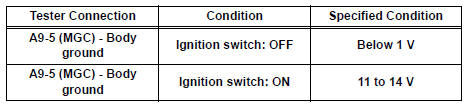

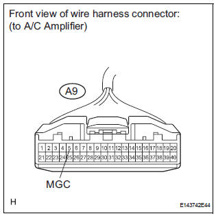
7 INSPECT A/C AMPLIFIER
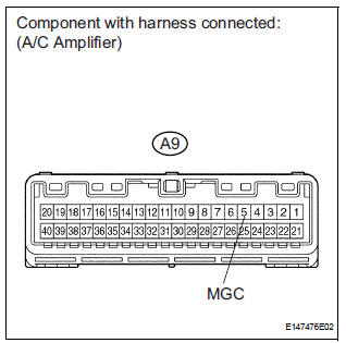
(a) Reconnect the connector to the A/C amplifier.
(b) Measure the voltage according to the value(s) in the table below.
Standard voltage 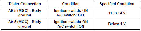

8 INSPECT COMPRESSOR AND MAGNETIC CLUTCH
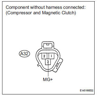
(a) Disconnect the connector from the compressor and magnetic clutch.
(b) Disconnect the connector from the magnetic clutch.
(c) Measure the resistance according to the value(s) in the table below.
Standard resistance 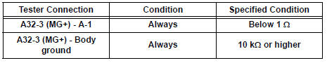

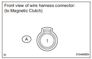
9 INSPECT MAGNETIC CLUTCH
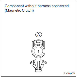
(a) Measure the resistance according to the value(s) in the table below.
Standard resistance 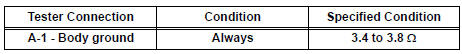
(b) When connector terminal A1 is connected to the positive (+) battery terminal, check that the following occurs: 1) the magnetic clutch's operating sound can be heard, and 2) the magnetic clutch's hub and rotor lock.


10 CHECK HARNESS AND CONNECTOR (NO. 3 RELAY BLOCK - BATTERY)
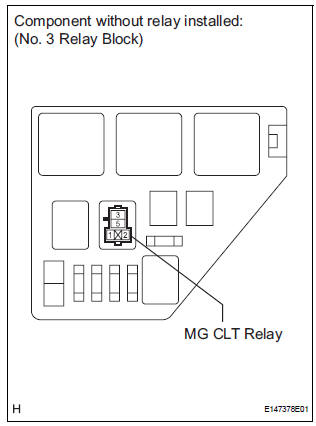
(a) Remove the MG CLT relay from the No. 3 relay block.
(b) Turn the ignition switch to the ON position.
(c) Measure the voltage according to the value(s) in the table below.
Standard voltage 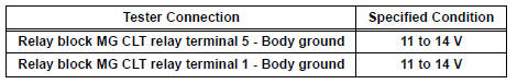

REPAIR OR REPLACE HARNESS OR CONNECTOR
 Blower Motor Circuit
DESCRIPTION
The blower motor is operated by signals from the A/C amplifier. Blower motor
speed signals are
transmitted by changes in the Duty Ratio.
Duty Ratio
The duty ratio is the ratio of ...
 Rear Air Conditioning Control Panel Circuit
DESCRIPTION
This is the rear A/C system control signal circuit as well as the power
supply circuit of the rear A/C control
assembly.
Pulse signals regarding rear A/C control panel switch operat ...
Other materials:
Inspection
1. Inspect no. 3 Intake air control valve
assembly
(A) inspect actuator operation.
(1) With 26.7 Kpa (200 mm hg, 7.9 In. Hg) of
vacuum applied to the actuator, check that the
actuator rod moves.
(2) One minute after applying the vacuum, check
that the actuator rod does not return.
...
Checking monitor status
The purpose of the monitor result (mode 06) is to allow
access to the results for on-board diagnostic monitoring tests
of specific components/systems that are not continuously
monitored. Examples are catalyst, evaporative emission
(EVAP) and thermostat.
The monitor result allows the OBD II sc ...
Display Panel does not Open, Tilt or Tilts Improperly
INSPECTION PROCEDURE
1 CHECK RADIO AND NAVIGATION ASSEMBLY
Check for foreign matter or obstructions caught in the
moving parts of the panel.
OK:
No obstruction or foreign matter found.
2 CHECK OPERATION
Check if the navigation and audio systems function
properly.
OK:
Naviga ...
