
Toyota Sienna Service Manual: Removal
1. DISCONNECT CABLE FROM NEGATIVE BATTERY TERMINAL
2. REMOVE FRONT DOOR SCUFF PLATE LH
3. REMOVE COWL SIDE TRIM SUB-ASSEMBLY LH
4. REMOVE LOWER INSTRUMENT PANEL FINISH PANEL SUB-ASSEMBLY LH (See page IP-6)
5. REMOVE TIRE PRESSURE WARNING RESET SWITCH
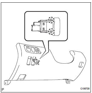
(a) Disengage the 2 claws and remove the tire pressure warning reset switch from the lower instrument panel finish panel sub-assembly LH.
 Tire pressure warning reset switch
COMPONENTS
...
 Inspection
1. INSPECT TIRE PRESSURE WARNING RESET SWITCH
(a) Remove the tire pressure warning reset switch.
(b) Measure the resistance between terminals 1 and 2
of the tire pressure warning reset switch ...
Other materials:
Removal
CAUTION:
Wear safety gloves, because the sharp surfaces of the
seatback frame and seat adjuster may injure your
hand.
Work must be started more than 90 seconds after the
ignition switch is turned to the LOCK position and the
negative (-) terminal cable is disconnected from ...
Diagnostic trouble code chart
1. DTCS FOR AIRBAG SYSTEM
If a malfunction code is displayed during the DTC check,
check the circuit listed for the code in the table below
(Proceed to the page listed for that circuit).
HINT:
When the SRS warning light remains on and the DTC
output is the normal system code, a volta ...
Data list / active test
1. READ DATA LIST
HINT:
Using the intelligent tester to read the Data List allows
the values or states of switches, sensors, actuators and
other items to be read without removing any parts. This
non-intrusive inspection can be very useful because
intermittent conditions or signals may be disco ...
