
Toyota Sienna Service Manual: Data list / active test
1. READ DATA LIST
HINT: Using the intelligent tester to read the Data List allows the values or states of switches, sensors, actuators and other items to be read without removing any parts. This non-intrusive inspection can be very useful because intermittent conditions or signals may be discovered before parts or wiring is disturbed. Reading the Data List information early in troubleshooting is one way to save diagnostic time.
- Connect the intelligent tester to DLC3.
- Turn the ignition switch to the ON position.
- According to the display on the tester, read the "DATA LIST".
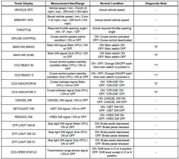
HINT: "3" is OK but "1" is NG → ECM failure "1" is OK but "2" is NG → DTC output or ECM failure "3" is OK but cruise indicator does not turn on → CRUISE MAIN indicator, wire harness, or ECM failure
2. PERFORM ACTIVE TEST
HINT: Using the intelligent tester to perform Active Tests allows relays, VSVs, actuators and other items to be operated without removing any parts. This non-intrusive functional inspection can be very useful because intermittent operation may be discovered before parts or wiring is disturbed. Performing Active Tests early in troubleshooting is one way to save diagnostic time. Data List information can be displayed while performing Active Tests.
- Connect the intelligent tester to the DLC3.
- Turn the ignition switch to the ON position.
- Perform the ACTIVE TEST according to the display on the tester.
HINT: The ignition switch must be turned on to proceed with the ACTIVE TEST using the intelligent tester.
Combination meter:

 Fail-safe chart
HINT:
If the following conditions are detected while the cruise
control is in operation, the system clears the stored vehicle
speed in the ECM and cancels the cruise control operation.
...
 Diagnostic trouble code chart
If a trouble code is indicated during the DTC check, check the
circuit listed for that code in the table below, and proceed to
the applicable page.
CRUISE CONTROL SYSTEM
...
Other materials:
Customize parameters
HINT:
The following items can be customized.
NOTICE:
After confirming whether the items requested by the
customer are applicable or not for customization,
perform customize operations.
Be sure to record the current settings before
customizing.
When troubleshooting, ...
Random / Multiple Cylinder Misfire Detected
DESCRIPTION
When the engine misfires, high concentrations of hydrocarbons (HC) enter the
exhaust gas. High HC
concentration levels can cause increase in exhaust emission levels. Extremely
high concentrations of HC
can also cause increases in the Three-Way Catalytic Converter (TWC) tem ...
Installation
1. INSTALL NAVIGATION ANTENNA ASSEMBLY
2. INSTALL INSTRUMENT PANEL SAFETY PAD SUBASSEMBLY
Using a torque wrench, install the bolt <B>.
Torque: 20 N*m (204 kgf*cm, 14 ft.*lbf)
3. INSTALL SHIFT LEVER ASSEMBLY
Using a torque wrench, install the 4 bolts.
Torque ...
