Toyota Sienna Service Manual: Removal
HINT: Remove the RH by the same procedure as the LH side.
1. REMOVE REAR WHEEL
2. SEPARATE SKID CONTROL SENSOR WIRE
(a) Disconnect the connector from the skid control sensor.
3. REMOVE REAR BRAKE DRUM SUB-ASSEMBLY (for Drum Type)
(a) Place matchmarks on the rear brake drum subassembly and the axle hub.
(b) Remove the rear brake drum sub-assembly.
4. REMOVE REAR DISC BRAKE CALIPER ASSEMBLY LH (for Disc Type)
(a) Remove the 2 bolts and rear brake caliper assembly LH.
5. REMOVE REAR DISC (for Disc Type)
(a) Place matchmarks on the rear disc and the axle hub.
(b) Remove the rear disc.
6. REMOVE REAR AXLE HUB & BEARING ASSEMBLY LH (See page AH-16)
7. REMOVE REAR SPEED SENSOR
(a) Mount the rear axle hub in a soft jaw vise.
NOTICE: Replace the axle hub assembly if it is dropped or a strong shock is given to it.
(b) Using a pin punch and hammer, drive out the 2 pins and remove the 2 attachments from SST.
(c) Using SST and 2 bolts (Diameter: 12 mm, pitch: 1.5 mm), remove the skid control sensor from the rear axle hub.
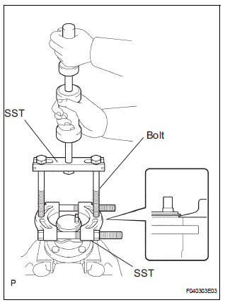
SST 09520-00031 (09520-00040), 09521-00020, 09950-00020
NOTICE:
- If a damage is inflicted to the sensor rotor is damaged, replace the axle hub assembly.
- Do not scratch the contacting surface of the axle hub and speed sensor.
 Rear speed sensor (for 2wd)
Components
...
 Inspection
1. INSPECT REAR SPEED SENSOR
(a) Disconnect the skid control sensor connector.
(b) Measure the resistance between terminals 1 and 2
of the skid control sensor connector.
OK:
Resistance:
le ...
Other materials:
Removal
1. PRECAUTION
CAUTION: Be sure to read "PRECAUTION" thoroughly before
servicing.
2. DISCONNECT CABLE FROM NEGATIVE BATTERY
TERMINAL
CAUTION:
Wait for 90 seconds after disconnecting the cable to
prevent the airbag working.
3. REMOVE STEERING WHEEL NO.3 COVER LOWER
Using a ...
Error in Picture Circuit/ No Current in Back-light/ Excess Current in
Back-light
DTC 34-10 Error in Picture Circuit
DTC 34-11 No Current in Back-light
DTC 34-12 Excess Current in Back-light
DESCRIPTION
DTC No.
DTC Detection Condition
Trouble Area
34-10
Error in power supply system for picture circuit
Radio and navigation assembly
...
Installation
1. INSTALL 3 POINT TYPE NO. 2 REAR SEAT BELT ASSEMBLY
Check the degree of tilt when the belt begins to lock
the ELR.
Check that the belt does not lock within 15 of
tilt in all directions but that the belt locks with
over 45 of tilt, when gently moving the
retractor.
If ...
