
Toyota Sienna Service Manual: Inspection
1. INSPECT REAR SPEED SENSOR
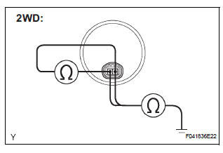
(a) Disconnect the skid control sensor connector.
(b) Measure the resistance between terminals 1 and 2 of the skid control sensor connector.
OK: Resistance: less than 2.2 kΩ
(c) Measure resistance between each of terminals 1 and 2 of the skid control sensor connector and body ground.
OK: Resistance: 1MΩ or higher
 Removal
HINT:
Remove the RH by the same procedure as the LH side.
1. REMOVE REAR WHEEL
2. SEPARATE SKID CONTROL SENSOR WIRE
(a) Disconnect the connector from the skid control
sensor.
3. REMOVE REAR ...
 Installation
HINT:
Install the RH side by the same procedure as the LH side.
1. INSTALL REAR SPEED SENSOR
(a) Clean the contacting surface of the axle hub and a
new skid control sensor.
NOTICE:
Keep the ...
Other materials:
Short to B+ in Door System Communication
Bus Malfunction/ Short to GND in Door System Communication
Bus Malfunction
DTC B1214 Short to B+ in Door System Communication
Bus Malfunction
DTC B1215 Short to GND in Door System Communication
Bus Malfunction
DESCRIPTION
DTCs B1214 and B1215 are output when a short to +B or the body ground occurs
on the communication
bus. Detecting this condition disables all the ...
Operation check
1. ILLUMINATED ENTRY SYSTEM OPERATION CHECK
The illuminated entry system is explained below:
Turn the ignition switch OFF, close all the doors,
and set them in the lock condition.
Unlock any door and open any other doors and
check that the room light comes on. Close ...
Terminals of ECU
1. POSITION CONTROL ECU AND SWITCH ASSEMBLY
(POWER SEAT CONTROL SWITCH AND ECU)
Disconnect the P58 and P59 connectors.
Check the voltage of each terminal of the wire
harness side connectors.
If the result is not as specified, there may be a
malfunction in the wire harn ...
