Toyota Sienna Service Manual: Removal
1. PRECAUTION
HINT: See page RS-1
2. DISCONNECT BATTERY NEGATIVE TERMINAL
Wait for 90 seconds after disconnecting the battery terminal to prevent the airbag working.
3. PLACE FRONT WHEELS FACING STRAIGHT AHEAD
4. REMOVE STEERING WHEEL COVER LOWER NO.2 (See page RS-424)
5. REMOVE STEERING WHEEL COVER LOWER NO.3 (See page RS-424)
6. REMOVE HORN BUTTON ASSEMBLY (See page RS- 424)
7. REMOVE STEERING WHEEL ASSEMBLY
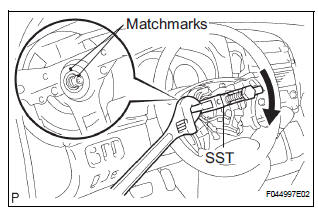
(a) Remove the steering wheel assembly set nut.
(b) Put matchmarks on the steering wheel assembly and main shaft assembly.
(c) Using SST, remove the steering wheel assembly.
SST 09950-50013 (09951-05010, 09952-05010, 09953-05020, 09954-05021)
8. REMOVE STEERING COLUMN COVER
(a) Remove the 2 screws and steering column cover.
9. REMOVE SPIRAL CABLE SUB-ASSEMBLY (See page RS-434)
10. REMOVE HEADLIGHT DIMMER SWITCH ASSEMBLY (See page LI-102)
11. REMOVE WINDSHIELD WIPER SWITCH ASSEMBLY (See page WW-17)
12. REMOVE FRONT DOOR SCUFF PLATE LH
13. REMOVE COWL SIDE TRIM BOARD LH
14. REMOVE INSTRUMENT PANEL FINISH PANEL SUBASSEMBLY LOWER LH (See page IP-6)
15. REMOVE INSTRUMENT PANEL SAFETY PAD INSERT SUB-ASSEMBLY NO.1 (See page IP-6)
16. REMOVE HEATER TO FOOT DUCT NO.3
(a) Disengage the 3 claws and remove the sir duct No.
3.
17. SEPARATE STEERING INTERMEDIATE SHAFT ASSEMBLY
(a) Loosen the bolt.
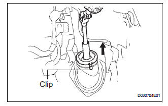
(b) Release the 3 clips and separate the dust cover.
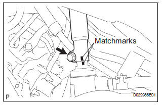
(c) Align the matchmarks on the steering intermediate shaft assembly and steering gear assembly.
(d) Remove the bolt and separate the steering intermediate shaft assembly.
18. REMOVE STEERING COLUMN ASSEMBLY
(a) Disconnect the connectors and wire harness clamps.
(b) Remove the 3 bolts and steering column assembly from the instrument panel reinforcement assembly.
 Steering Column Assembly
COMPONENTS
...
 Disassembly
1. REMOVE STEERING INTERMEDIATE SHAFT ASSEMBLY
(a) Align the matchmarks on the steering intermediate
shaft assembly and main shaft.
(b) Remove the bolt and steering intermediate shaft
assemb ...
Other materials:
Diagnostic trouble code chart
1. DTCS FOR OCCUPANT CLASSIFICATION SYSTEM
If a trouble code is displayed during the DTC check,
check the circuit listed for the code in the table below
(proceed to the page listed for that circuit).
HINT:
When DTC B1150/23 is detected as a result of
troubleshooting for the airbag system, pe ...
Installation
1. INSTALL TRANSMISSION WIRE
(a) Coat the O-ring of the transmission wire connector
with ATF and install it.
(b) Install the transmission wire with the bolt.
Torque: 5.4 N*m (55 kgf*cm, 48 ft.*lbf)
2. CONNECT TRANSMISSION WIRE
(a) Coat the O-ring of the ATF temperature sensor with
...
Precaution
1. HANDLING PRECAUTIONS ON STEERING SYSTEM
(a) Be careful to replace the parts properly because
they could affect the performance of the steering
system and result in a driving hazard.
2. HANDLING PRECAUTIONS ON SRS AIRBAG
SYSTEM
(a) The SIENNA is equipped with SRS (Supplemental
Restraint Sys ...
