Toyota Sienna Service Manual: Disassembly
1. REMOVE STEERING INTERMEDIATE SHAFT ASSEMBLY
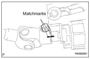
(a) Align the matchmarks on the steering intermediate shaft assembly and main shaft.
(b) Remove the bolt and steering intermediate shaft assembly.
2. REMOVE KEY CYLINDER LIGHT ASSEMBLY (w/o Engine Immobiliser System)
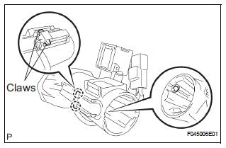
3. REMOVE TRANSPONDER KEY AMPLIFIER (w/ Engine Immobiliser System)
(a) Widen the claw hanging onto the upper bracket by approx. 1.0 mm (0.039 in.) using a screwdriver.
(b) Pull the transponder key amplifier toward the rear of the vehicle with the claw open.
NOTICE: Take care not to use excessive force to prevent the case from being damaged.
4. REMOVE STEERING COLUMN BRACKET ASSEMBLY UPPER
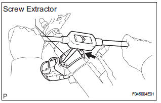
(a) Using a centering punch, mark the center of the 2 tapered-head bolts.
(b) Using a 3 to 4 mm (0.12 to 0.16 in.) drill, drill a hole into the heads of the 2 bolts.
(c) Using a screw extractor, remove the 2 bolts and steering column upper w/ switch bracket assembly.
5. REMOVE IGNITION SWITCH LOCK CYLINDER ASSEMBLY
(a) Place the ignition switch lock cylinder assembly in the ACC position.
(b) Push down the stop pin with a screwdriver, and pull out the cylinder assembly.
6. REMOVE UN-LOCK WARNING SWITCH ASSEMBLY
(a) Disconnect the un-lock warning switch assembly connector from the ignition or starter switch assembly.
(b) Remove the un-lock warning switch assembly by pushing up the center part and releasing the 2 claws.
(c) Disengage the secondary locking device.
(d) Using a screwdriver, disengage the locking lug of terminals 1 and 2, and pull the terminals out from the rear side of the un-lock warning switch assembly.
7. REMOVE KEY INTER LOCK SOLENOID
(a) Remove the 2 screws and solenoid from the steering column bracket assembly.
8. REMOVE IGNITION OR STARTER SWITCH ASSEMBLY
(a) Remove the 2 screws and ignition or starter switch assembly from the steering column bracket assembly UPR.
 Removal
1. PRECAUTION
HINT:
See page RS-1
2. DISCONNECT BATTERY NEGATIVE TERMINAL
Wait for 90 seconds after disconnecting the battery
terminal to prevent the airbag working.
3. PLACE FRONT WHEELS FACING ...
 Reassembly
1. INSTALL IGNITION OR STARTER SWITCH
ASSEMBLY
(a) Install the ignition or starter switch assembly to the
steering column bracket assembly UPR with the 2
screws.
2. INSTALL KEY INTER LOCK SOLENOI ...
Other materials:
Disposal
HINT:
When scrapping a vehicle equipped with the SRS or
disposing of the front passenger airbag assembly, be sure to
deploy the airbag first in accordance with the procedure
described below. If any abnormality occurs with airbag
deployment, contact the SERVICE DEPT. of the TOYOTA
MOTOR SALES, ...
Transmitter ID1 Error
DESCRIPTION
The tire pressure warning valve and transmitters that are installed in the
tire and wheel assemblies
measure the air pressure of the tires. The measured values are transmitted to
the tire pressure warning
antenna and receiver on the body as radio waves and then sent to the tir ...
Washer Signal Circuit
DESCRIPTION
The distance control ECU detects washer operation. The cruise control will be
cancelled by the distance
control ECU if the windshield wipers operate in the HI or LO mode. By detecting
washer operation, the
distance control ECU allows the cruise control to continue even when the
...
