
Toyota Sienna Service Manual: On-vehicle inspection
1. INSPECT FOR FUEL PUMP OPERATION AND FUEL LEAK
(a) Check fuel pump operation.
(1) Connect the intelligent tester to the DLC3.
(2) Turn the engine switch on (IG) and push the intelligent tester main switch on.
| NOTICE: Do not start the engine. |
(3) Select the following menu items: DIAGNOSIS / ENHANCED OBD II / ACTIVE TEST / FUEL PUMP / SPD.
(4) Check for pressure in the fuel inlet tube from the fuel line. Check that sound of fuel flowing in the fuel tank can be heard. If no sound can be heard, check the integration relay, fuel pump, ECM and wiring connector.
(b) Check for fuel leaks (*1).
(1) Check that there are no fuel leaks anywhere on the system after performing maintenance. If there is a fuel leak, repair or replace parts as necessary.
(c) Turn the engine switch off.
(d) Disconnect the intelligent tester from the DLC3.
2. CHECK FUEL PRESSURE
(a) Discharge the fuel system pressure (See page FU- 1).
(b) Using a voltmeter, measure the battery voltage.
Standard voltage: 11 to 14 V
(c) Disconnect the cable from the negative (-) battery terminal.
(d) Disconnect the fuel hose from the fuel main tube (See page FU-1).
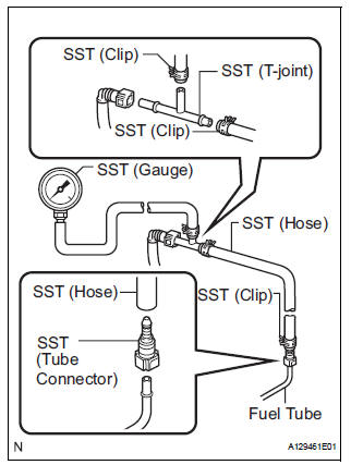
(e) Install SST (pressure gauge) using SST and a fuel tube connector as shown in the illustration.
SST 09268-31011 (09268-41500, 90467-13001, 95336-08070), 09268-45014 (09268-41200, 09268-41220, 09268-41250)
(f) Wipe up any gasoline.
(g) Connect the cable to the negative (-) battery terminal.
(h) Connect the intelligent tester to the DLC3.
(i) Select the following menu items: DIAGNOSIS / ENHANCED OBD II / ACTIVE TEST / FUEL PUMP / SPD.
(j) Measure the fuel pressure.
Fuel pressure: 304 to 343 kPa (3.1 to 3.5 kgf*cm2, 44.1 to 49.7 psi)
- If the fuel pressure is greater than the standard value, replace the fuel pressure regulator.
- If the fuel pressure is less than the standard value, check the fuel hoses and connections, fuel pump, fuel filter and fuel pressure regulator.
(k) Disconnect the intelligent tester from the DLC3.
(l) Start the engine.
(m) Measure the fuel pressure at idle.
Fuel pressure: 304 to 343 kPa (3.1 to 3.5 kgf*cm2, 44.1 to 49.7 psi)
(n) Stop the engine.
(o) Check that the fuel pressure remains as specified for 5 minutes after the engine stops.
Fuel pressure: 147 kPa (1.5 kgf*cm2, 21 psi) or more
If the fuel pressure is not as specified, check the fuel pump, pressure regulator and/or fuel injectors.
(p) After checking the fuel pressure, disconnect the cable from the negative (-) battery terminal and carefully remove the SST to prevent gasoline from splashing.
(q) Reconnect the fuel tube to the main fuel tube (fuel tube connector).
(r) Install the No. 1 fuel pipe clamp to the fuel tube connector.
(s) Check for fuel leaks (*1).
 Precaution
1. PRECAUTION
(a) Before inspecting and repairing the fuel system,
disconnect the cable from the negative (-) battery
terminal.
(b) Do not smoke or work near fire when handling the
fuel system. ...
 Fuel injector
...
Other materials:
Installation
1. INSTALL OCCUPANT CLASSIFICATION ECU
Check that the ignition switch is off.
Check that the negative battery (-) terminal is
disconnected.
CAUTION:
After disconnecting the negative battery
terminal, wait for at least 90 seconds before
starting the operation.
...
Gyro Error
DTC 58-10 Gyro Error
DTC 80-10 Gyro Error
DESCRIPTION
DTC No.
DTC Detection Condition
Trouble Area
58-10
Ground short, power supply short, or open circuit in the
gyro signal
Gyro sensor
Radio and navigation assembly
80-10
...
Installation
1. INSTALL TIRE PRESSURE WARNING RESET SWITCH
(a) Engage the 2 claws to install the tire pressure
warning reset switch to the lower instrument panel
finish panel sub-assembly LH.
2. INSTALL LOWER INSTRUMENT PANEL FINISH
PANEL SUB-ASSEMBLY LH
3. INSTALL COWL SIDE TRIM SUB-ASSEMBLY LH
4. IN ...
