Toyota Sienna Service Manual: Reassembly
1. INSTALL UNDERDRIVE CLUTCH DRUM O-RING
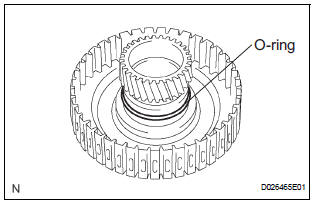
(a) Coat a new O-ring with ATF, and install it to the underdrive clutch drum.
NOTICE: Make sure that the O-ring is not twisted or pinched.
2. INSTALL UNDERDRIVE CLUTCH PISTON SET
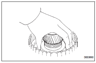
(a) Coat the underdrive clutch piston with ATF, and install it to the underdrive clutch piston drum.
NOTICE:
- Be careful not to damage the O-ring.
- Be careful not to damage the lip of the piston.
3. INSTALL UNDERDRIVE CLUTCH RETURN SPRING SUB-ASSEMBLY
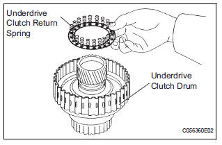
(a) Install the return spring to the underdrive clutch drum.
NOTICE: Installing the spring sub-assembly, check that all of the springs are fit in the piston correctly.
(b) Coat the clutch balancer with ATF.
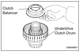
(c) Install the clutch balancer to the underdrive clutch drum.
NOTICE: Be careful not to damage the lip of the clutch balancer.
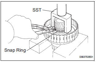
(d) Place SST on the clutch balancer and compress the piston return spring with a press.
SST 09350-32014 (09351-32070)
(e) Using a snap ring expander, install the snap ring to the underdrive clutch drum.
(f) Be sure that the end gap of the snap ring is not aligned with the spring retainer claw.
NOTICE:
- Stop the press when the spring seat is lowered to the place 1 to 2 mm (0.039 to 0.078 in.) from the snap ring groove.
- This prevents the spring seat from being deformed
- Do not expand the snap ring excessively.
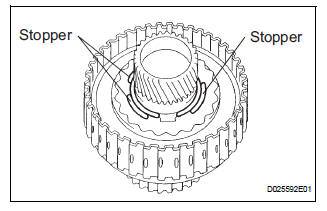
(g) Set the end gap of the snap ring in the underdrive clutch drum as shown in the illustration.
NOTICE: The end gap of the snap ring should not align with any of the stoppers.
4. INSTALL UNDERDRIVE CLUTCH DISC NO.1
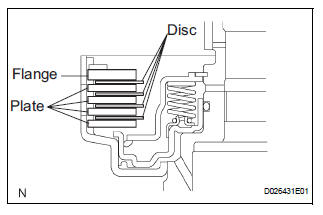
(a) Coat the 4 discs with ATF.
(b) Install the 4 plates, 4 discs and flange to the underdrive clutch drum.
NOTICE: Make sure that the plates, discs, and flange are installed as shown in the illustration.
5. INSTALL 1ST & REVERSE BRAKE RETURN SPRING SHAFT SNAP RING
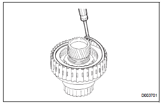
(a) Using a screwdriver, install the underdrive clutch flange No.2 hole snap ring.
(b) Check that the end gap of snap ring is not aligned with one of the cutouts.
NOTICE: The snap ring should be fully engaged in the groove of the drum.
6. INSPECT UNDERDRIVE PACK CLEARANCE
HINT: (See page AX-262)
 Inspection
1. INSPECT UNDERDRIVE PACK CLEARANCE
(a) Install the underdrive clutch to the transaxle case.
NOTICE:
Be careful not to damage the oil seal rings.
(b) Install a dial indicator as shown in the ...
 Differential case
COMPONENTS
...
Other materials:
Checking monitor status
The purpose of the monitor result (mode 06) is to allow
access to the results for on-board diagnostic monitoring tests
of specific components/systems that are not continuously
monitored. Examples are catalyst, evaporative emission
(EVAP) and thermostat.
The monitor result allows the OBD II sc ...
Inspection
1. INSPECT FRONT SEAT INNER BELT ASSEMBLY RH
Release the seat belt (Buckle switch is ON).
Check the resistance between the terminals.
Standard
If the result is not as specified, replace the inner belt
assembly.
Inspect the buckle switch.
Fasten ...
Actuator Supply Voltage Circuit / Open
DTC P0657 Actuator Supply Voltage Circuit / Open
DESCRIPTION
The ECM monitors the output voltage to the throttle actuator. This self-check
ensures that the ECM is
functioning properly. The output voltage is usually 0 V when the ignition switch
is turned off. If the output
voltage is higher t ...
