Toyota Sienna Service Manual: Installation
1. INSTALL AMPLIFIER ANTENNA ASSEMBLY
- Engage the 16 clamps to install the amplifier antenna assembly.
- Install the 3 bolts.
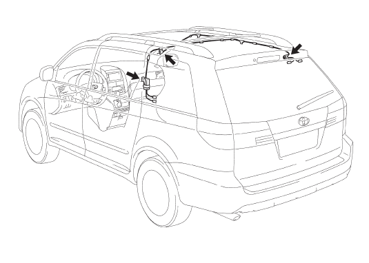
- Connect the connectors.
2. INSTALL ROOF HEADLINING ASSEMBLY
3. INSTALL ANTENNA ASSEMBLY WITH HOLDER
- Install the antenna assembly with holder with the nut.
- Install the bolt and connect the connector.
4. INSTALL ANTENNA ORNAMENT
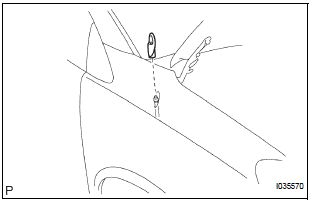
- Install the antenna ornament.
5. INSTALL PULL TOP ANTENNA POLE SUBASSEMBLY
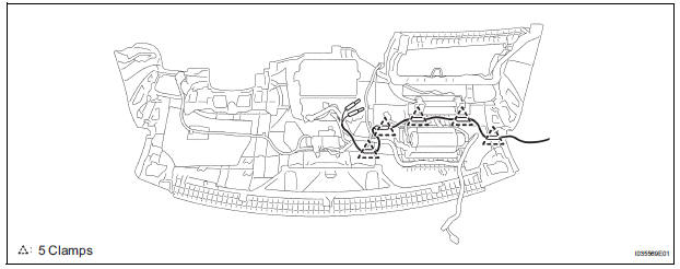
6. INSTALL ANTENNA CORD SUB-ASSEMBLY
- Engage the 5 clamps to install the antenna cord sub-assembly.
7. INSTALL INSTRUMENT PANEL SAFETY PAD SUBASSEMBLY
 Removal
1. REMOVE INSTRUMENT PANEL SAFETY PAD SUBASSEMBLY
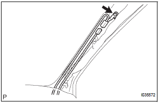
2. REMOVE ANTENNA CORD SUB-ASSEMBLY
Replace the 5 clamps and remove the antenna cord
sub-assembly.
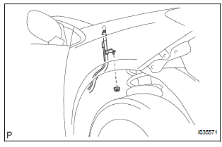
3. REMOVE PULL TOP ANTENNA POLE S ...
 Radio antenna pole
COMPONENTS
REMOVAL
1. REMOVE PULL TOP ANTENNA POLE SUBASSEMBLY
Remove the pull top antenna pole sub-assembly by
pulling it the arrow direction in the illustration.
INSTALLATION
...
Other materials:
Installation with LATCH system (second seat)
Fold the seatback while pulling
the lever and move to the rearmost
recline position.
Widen the gap between the seat cushion and seatback slightly.
Type A
Latch the hooks of the lower
straps onto the LATCH
anchors. If the child restraint
has a top tether strap, the ...
Driving position memory
Your preferred driving position (the position of the driverÔÇÖs seat and
outside rear view mirrors) can be recalled by pressing a button.
Two different driving positions can be recorded into memory.
Recording procedure
Check that the shift lever is in P.
Turn the engine switch to IGNI ...
Selecting the audio
source
Switching between audio sources such as radio and CD are
explained in this section.
Changing audio source
Press the ÔÇťAUDIOÔÇŁ button to display the audio source selection
screen.
If the audio source selection screen is not displayed, press the ÔÇťAUDIOÔÇŁ
button again.
Select the des ...
