Toyota Sienna Service Manual: Removal
1. REMOVE WINDSHIELD WIPER MOTOR ASSEMBLY
2. REMOVE FRONT OUTER COWL TOP PANEL SUBASSEMBLY
3. DRAIN ENGINE COOLANT
4. REMOVE V-BANK COVER SUB-ASSEMBLY
5. REMOVE NO. 2 AIR CLEANER INLET
6. REMOVE NO. 1 AIR CLEANER INLET
7. REMOVE AIR CLEANER CAP SUB-ASSEMBLY
- Disconnect the 3 vacuum hoses.
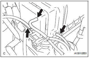
- Remove the No. 2 ventilation hose and air cleaner hose band.
- Disconnect the vacuum hose (EVAP) from the air cleaner hose.
- Disconnect the mass air flow meter connector.
- Remove the 2 bolts and air cleaner cap subassembly.
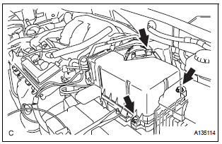
8. REMOVE AIR CLEANER CASE SUB-ASSEMBLY
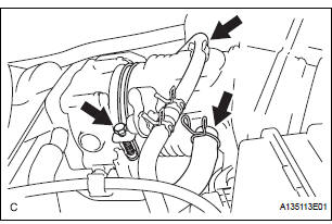
9. REMOVE THROTTLE BODY
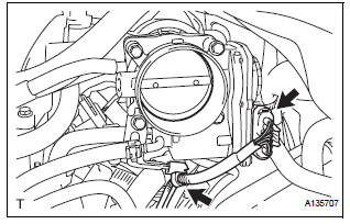
- Disconnect the throttle body connector and clamp.
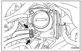
- Disconnect the 2 water by-pass hoses from the throttle body.
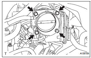
- Remove the 4 bolts and throttle body.
- Remove the throttle body gasket from the intake air surge tank.
 On-vehicle inspection
1. INSPECT THROTTLE BODY
Listen to the throttle control motor operating sounds.
Turn the ignition switch to the ON position.
When pressing the accelerator pedal position
sens ...
 Inspection
1. INSPECT THROTTLE BODY
Using an ohmmeter, measure the resistance
between the terminals.
Standard resistance
If the result is not as specified, replace the throttle
body asse ...
Other materials:
Ignition key cylinder light
ON-VEHICLE INSPECTION
1. KEY CYLINDER LIGHT ASSEMBLY
Connect the battery positive (+) lead to the terminal
1 and the battery negative (-) lead to the terminal 2,
and check that the indicator light comes on.
2. TRANSPONDER KEY AMPLIFIER
Inspect key cylinder light o ...
Display Signal Circuit between Radio and Navigation Assembly and
Television Camera Assembly
DESCRIPTION
This is the display signal circuit of the television camera assembly.
WIRING DIAGRAM
INSPECTION PROCEDURE
1 CHECK HARNESS AND CONNECTOR (RADIO AND NAVIGATION ASSEMBLY - TELEVISION
CAMERA ASSEMBLY)
Disconnect the R10 connector from the radio and
navigation assembly.
&nbs ...
Preparation 2gr-fe engine mechanical
SST
RECOMMENDED TOOLS
EQUIPMENT
HINT:
Torx is registered trademark of Textron Inc.
SSM
...
