
Toyota Sienna Service Manual: Removal
1. REMOVE GLOVE COMPARTMENT DOOR ASSEMBLY
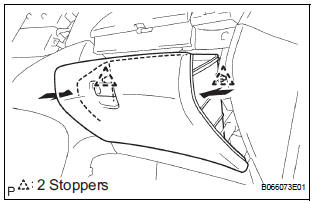
- Push the right side wall and then push the left wall to release the stoppers.
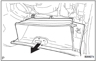
- Pull the glove compartment door sub-assembly rearward to remove it.
2. REMOVE NO. 2 INSTRUMENT PANEL BOX
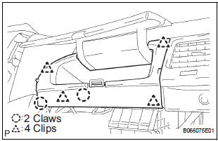
- Disengage the 2 claws and 4 clips, and remove the No. 2 instrument panel box.
3. REMOVE ECM
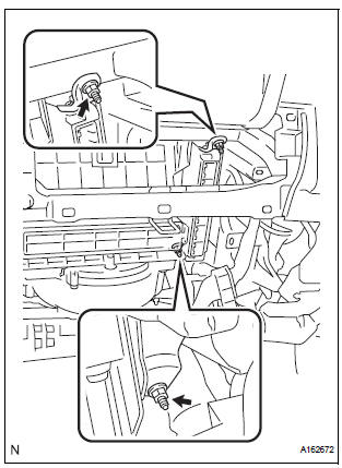
- Disconnect the 5 ECM connectors.
- Remove the 2 nuts and ECM.
4. REMOVE ECM (with 10 speakers system)
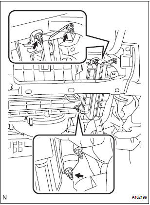
- Disconnect the 5 ECM connectors and 2 stereo components amplifier connectors.
- Remove the 4 nuts and the ECM with the stereo components amplifier.
 ECM
ECM
Components
...
 Installation
1. INSTALL ECM
Install the ECM with the 2 nuts.
Torque: 5.5 N*m (56 kgf*cm, 49 in.*lbf)
Connect the 5 ECM connectors.
2. INSTALL ECM (with 10 speakers system)
...
Other materials:
Wrong Disc/ Disc cannot be Read
DTC 44-41 Wrong Disc
DTC 44-42 Disc cannot be Read
DESCRIPTION
DTC No.
DTC Detection Condition
Trouble Area
44-41
An unsuitable disc is inserted
DVD
Television display assembly
44-42
The disc cannot be read.
INSPECTION ...
Terminals of ECU
1. MULTIPLEX NETWORK GATEWAY ECU
Disconnect the G4 ECU connector.
Measure the voltage between the specified
terminals on the wire harness side connector.
If the result is not as specified, there may be a
malfunction on the wire harness side.
Measure the resistance between ...
Removing the second seats
Removing the second outside seats (Tip-up seats)
Pull the armrests up.
Pull the seatback adjustment
lever and fold down the seatback.
The cushion will tip up.
Slide the seat forward to a lock position.
Pull the release lever under
the cushion and simultaneously
lift the ...
