Toyota Sienna Service Manual: Steering Pad Switch Circuit
DESCRIPTION
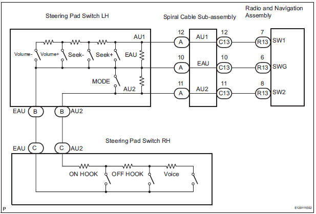
This circuit sends an operation signal from the steering pad switch to the radio receiver.
If there is an open in the circuit, the navigation system cannot be operated using the steering pad switch.
If there is a short in the circuit, the resulting condition is the same as if the switch were continuously depressed. Therefore, the radio and navigation assembly cannot be operated using the steering pad switch, and the radio and navigation assembly itself cannot function.
WIRING DIAGRAM
INSPECTION PROCEDURE
NOTICE: The vehicle is equipped with an SRS (Supplemental Restraint System) such as the airbags. Before servicing (including removal or installation of parts), be sure to read the precautionary notice for the Supplemental Restraint System (
1 INSPECT RADIO AND NAVIGATION ASSEMBLY
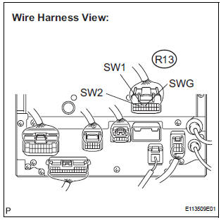
- Disconnect the radio and navigation assembly connector R13.
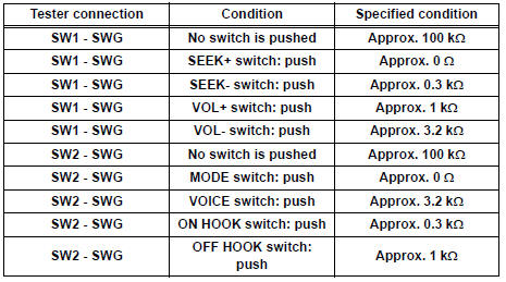
- Measure the resistance according to the value(s) in the table below.
Standard resistance
PROCEED TO NEXT CIRCUIT INSPECTION SHOWN IN PROBLEM SYMPTOMS TABLE
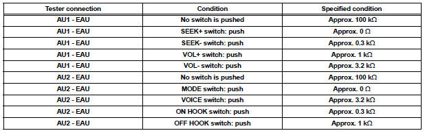
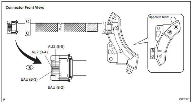
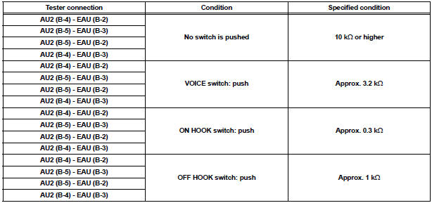
2 INSPECT STEERING PAD SWITCH ASSEMBLY
- Disconnect the steering pad switch assembly connector A.
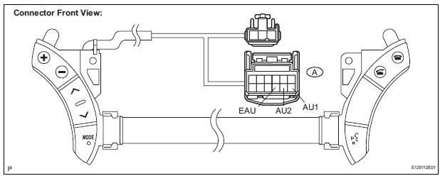
- Measure the resistance according to the value(s) in the table below.
Standard resistance
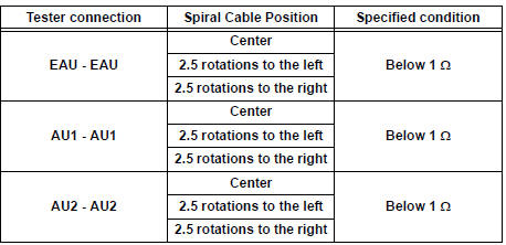
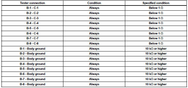
3 INSPECT SPIRAL CABLE SUB-ASSEMBLY
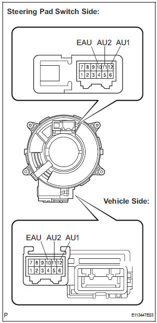
- Disconnect the steering pad switch assembly and spiral cable sub-assembly connectors.
- Measure the resistance according to the value(s) in the table below.
Standard resistance
NOTICE: The spiral cable is an important part of the SRS airbag system. Incorrect removal or installation of the spiral cable may prevent the airbag from deploying. Be sure to read the page shown in the brackets
REPAIR OR REPLACE HARNESS OR CONNECTOR (SPIRAL CABLE SUB-ASSEMBLY - RADIO AND NAVIGATION ASSEMBLY)
4 INSPECT STEERING PAD SWITCH CABLE
- Disconnect the steering pad switch LH and the steering pad switch RH.
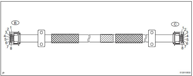
- Measure the resistance according to the value(s) in the table below
Standard resistance
5 INSPECT STEERING PAD SWITCH RH
- Reconnect the steering pad switch RH.
- Measure the resistance according to the value(s) in the table below.
Standard resistance
REPLACE STEERING PAD SWITCH LH
 Vehicle Speed Signal Circuit between Radio and Navigation Assembly
and Combination Meter
Vehicle Speed Signal Circuit between Radio and Navigation Assembly
and Combination Meter
DESCRIPTION
The radio and navigation assembly receives a vehicle speed signal from the
combination meter and
information about the GPS antenna, and then adjusts vehicle position.
HINT:
...
 Illumination Circuit
DESCRIPTION
Power is supplied to the radio and navigation assembly and steering pad
switch illumination when the
light control switch is in the TAIL or HEAD position.
WIRING DIAGRAM
INSPECTI ...
Other materials:
Air Mix Damper Control Servo Motor Circuit (Passenger Side)
DESCRIPTION
The air mix control servo motor (air mix damper servo sub-assembly) is
controlled by the A/C amplifier.
The air mix control servo motor moves the air mix damper by rotating (normal,
reverse) with electrical
power from the A/C amplifier.
This adjusts the mix ratio of the air t ...
Door LOCK Position Circuit
DESCRIPTION
This circuit detects the state of the door lock detection sensor and send it
to the Multiplex network body
ECU.
WIRING DIAGRAM
INSPECTION PROCEDURE
1 READ VALUE OF INTELLIGENT TESTER
Connect the intelligent tester to DLC3.
Turn the ignition switch ON and push the i ...
Oxygen (A/F) Sensor Signal Stuck
DTC P2195 Oxygen (A/F) Sensor Signal Stuck Lean (Bank 1
Sensor 1)
DTC P2196 Oxygen (A/F) Sensor Signal Stuck Rich (Bank 1
Sensor 1)
DTC P2197 Oxygen (A/F) Sensor Signal Stuck Lean (Bank 2
Sensor 1)
DTC P2198 Oxygen (A/F) Sensor Signal Stuck Rich (Bank 2
Sensor 1)
HINT:
Although the ...
