Toyota Sienna Service Manual: Removal
1. DISCONNECT CABLE FROM NEGATIVE BATTERY TERMINAL
2. REMOVE REAR NO. 2 SEAT LEG SIDE GARNISH SUB-ASSEMBLY
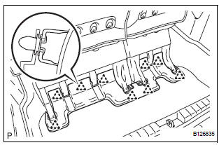
- Disengage the 9 clips and remove the rear No. 2 seat leg side garnish sub-assembly.
- Remove the 9 clips from the rear No. 2 seat leg side garnish sub-assembly.
3. REMOVE REAR SEAT LEG SIDE GARNISH SUBASSEMBLY
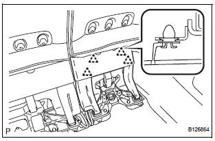
- Disengage the 4 clips and remove the rear seat leg side garnish sub-assembly.
- Remove the 4 clips from the rear seat leg side garnish sub-assembly.
4. REMOVE NO. 2 SEAT HINGE COVER
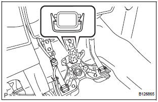
- Disengage the 4 claws and remove the No. 2 seat hinge cover.
5. REMOVE REAR NO. 2 SEAT ASSEMBLY
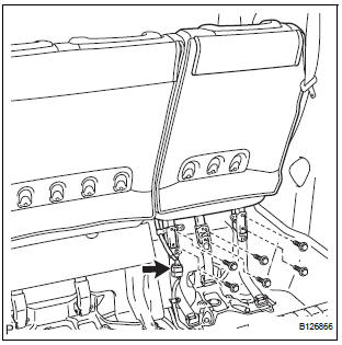
- Disconnect the connector.
- Remove the 6 bolts.
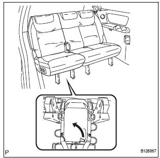
- Pull the lever under the No. 2 seat cushion subassembly and remove the rear No. 2 seat assembly
 Rear no. 2 Seat assembly (for Power Seat Type RH Side)
COMPONENTS
...
 Disassembly
1. REMOVE REAR NO. 2 SEAT COVER BEZEL
Remove the 3 screws.
Disengage the 3 claws and remove the rear No. 2
seat cover bezel.
2. REMOVE REAR SEAT RECLINING COVER RH
& ...
Other materials:
Transmission Error
DTC 01-DC Transmission Error
DESCRIPTION
HINT:
*1: This code may be stored if the engine is started, idled for 60 seconds and
then started again.
NOTICE:
Before starting troubleshooting, be sure to clear DTCs to erase
codes stored due to the
reasons described in the HINT ...
Installation
1. Install generator assembly
(a) Install the bracket with the bolt.
Torque: 20 N*m (204 kgf*cm, 15 ft.*lbf)
(b) Install the wire harness clamp stay.
Torque: 8.4 N*m (86 kgf*cm, 74 in.*lbf)
(c) Connect the wire harness clamp.
(d) Install the generator assembly to the cylinder ...
Removal
1. REMOVE INSTRUMENT PANEL SAFETY PAD SUBASSEMBLY
2. REMOVE ANTENNA CORD SUB-ASSEMBLY
Replace the 5 clamps and remove the antenna cord
sub-assembly.
3. REMOVE PULL TOP ANTENNA POLE SUBASSEMBLY
4. REMOVE ANTENNA ORNAMENT
Remove the antenna ornament.
5. REMOVE ANTENNA ASS ...
