Toyota Sienna Service Manual: Disassembly
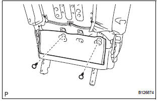
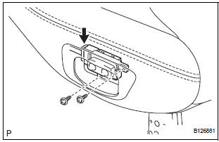
1. REMOVE REAR NO. 2 SEAT COVER BEZEL
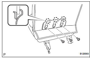
- Remove the 3 screws.
- Disengage the 3 claws and remove the rear No. 2 seat cover bezel.
2. REMOVE REAR SEAT RECLINING COVER RH
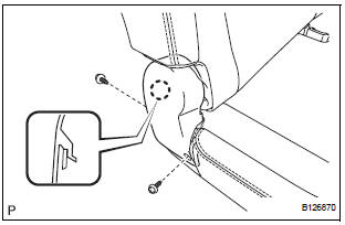
- Remove the 2 screws.
- Disengage the claw and remove the rear seat reclining cover RH.
3. REMOVE REAR SEAT RECLINING COVER LH
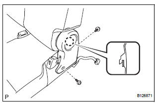
- Remove the 2 screws.
- Disengage the claw and remove the rear seat reclining cover LH.
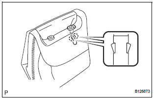
4. REMOVE REAR SEAT HEADREST ASSEMBLY
5. REMOVE REAR NO. 2 SEAT HEADREST SUPPORT ASSEMBLY LH
- Remove the pad.
- Remove the 2 clips.
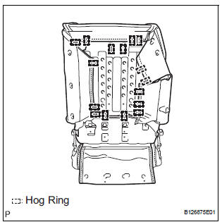
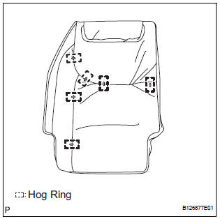
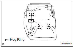
- Remove the 16 hog rings and disconnect the No. 2 seatback cover sub-assembly with pad.
- Turn back the No. 2 seatback cover sub-assembly.
- Disengage the 2 claws and remove the rear No. 2 seat headrest support assembly LH.
6. REMOVE REAR NO. 2 SEAT HEADREST SUPPORT ASSEMBLY RH
HINT: Use the same procedure described for the LH side.
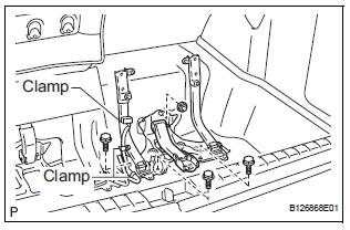
7. REMOVE NO. 2 SEATBACK COVER SUB-ASSEMBLY WITH PAD
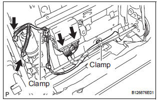
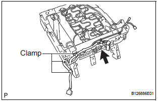
- Disconnect the connectors.
- Disengage the 3 clamps and remove the No. 2 seatback cover sub-assembly with pad
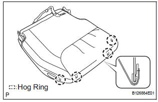
8. REMOVE NO. 2 SEATBACK COVER SUB-ASSEMBLY
- Remove the 6 hog rings and No. 2 seatback cover sub-assembly.
9. REMOVE NO. 2 SEATBACK PAD
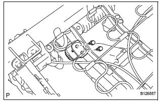
10. REMOVE FOLD SEAT CONTROL ECU
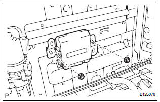
- Remove the 2 nuts and fold seat control ECU.
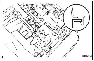
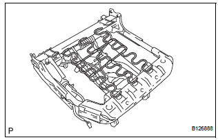
11. REMOVE NO. 2 SEATBACK FRAME SUB-ASSEMBLY
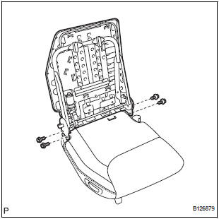
- Remove the 4 bolts and No. 2 seatback frame subassembly
12. REMOVE RECLINING REMOTE CONTROL LEVER BEZEL
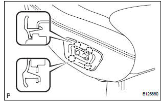
- Disengage the 4 claws and remove the reclining remote control lever bezel.
13. REMOVE REAR POWER SEAT SWITCH
- Remove the 2 screws.
- Disconnect the connector and remove the rear power seat switch.
14. REMOVE REAR NO. 2 SEAT BELT ASSEMBLY INNER
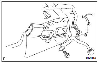
- Remove the bolt, washer and rear No. 2 seat belt assembly inner.
15. REMOVE REAR SEAT COVER
- Remove the 2 screws.
- Disengage the 2 claws and remove the rear seat cover.
16. REMOVE NO. 2 SEAT CUSHION COVER SUBASSEMBLY WITH PAD
- Raise the 4 rear seat cushion edge protectors.
- Disengage the hooks and remove the No. 2 seat cushion cover sub-assembly with pad.
17. REMOVE NO. 2 SEAT CUSHION COVER SUBASSEMBLY
- Remove the 6 hog rings and No. 2 seat cushion cover sub-assembly.
18. REMOVE NO. 2 SEAT CUSHION PAD
19. REMOVE REAR SEAT WIRE
- Disconnect the connector.
- Disengage the 3 clamps and remove the rear seat wire.
20. REMOVE NO. 2 SEAT CUSHION STOPPER
- Remove the 2 bolts and No. 2 seat cushion stopper.
HINT: Use the same procedure to remove the other stopper.
21. REMOVE NO. 2 SEAT CUSHION SPRING ASSEMBLY
- Remove the No. 2 seat cushion spring assembly.
22. REMOVE NO. 2 SEAT CUSHION FRAME SUBASSEMBLY
23. REMOVE NO. 2 SEAT LEG SUB-ASSEMBLY
- Disengage the 3 clamps.
- Remove the 3 bolts, nut and No. 2 seat leg subassembly.
 Removal
1. DISCONNECT CABLE FROM NEGATIVE BATTERY
TERMINAL
2. REMOVE REAR NO. 2 SEAT LEG SIDE GARNISH SUB-ASSEMBLY
Disengage the 9 clips and remove the rear No. 2
seat leg side garnish sub-a ...
 Adjustment
HINT:
If the malfunction does not disappear by following the
procedure in ADJUSTMENT and the rear No. 2 seat
assembly needs to be replaced, do not disassemble the rear
No. 2 seat assembly.
1. ADJ ...
Other materials:
Rear Occupant Classification Sensor LH Circuit
Malfunction
DTC B1782 Rear Occupant Classification Sensor LH Circuit
Malfunction
DESCRIPTION
The rear occupant classification sensor LH circuit consists of the occupant
classification ECU and the rear
occupant classification sensor LH.
DTC B1782 is recorded when a malfunction is detected in the rear oc ...
Insufficient Coolant Temperature for Closed Loop Fuel Control
DESCRIPTION
Refer to DTC P0115 (See page ES-133).
MONITOR DESCRIPTION
The resistance of the ECT sensor varies in proportion to the actual ECT. The
ECM supplies a constant
voltage to the sensor and monitors the signal output voltage of the sensor. The
signal voltage output
varies acc ...
Removal
HINT:
Use the same procedures for the RH side and LH side.
The procedures listed below are for the LH side.
1. PRECAUTION
CAUTION:
Be sure to read "PRECAUTION" thoroughly before servicing.
2. DISCONNECT CABLE FROM NEGATIVE BATTERY
TERMINAL
CAUTION:
Wait for 90 se ...
