Toyota Sienna Service Manual: Installation
1. INSTALL KNOCK CONTROL SENSOR
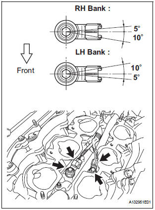
- Install the 2 knock control sensors with the 2 bolts
as shown in the illustration.
Torque: 20 N*m (204 kgf*cm, 15 ft.*lbf)
- Connect the 2 knock control sensor connectors.
2. INSTALL INTAKE MANIFOLD
3. INSTALL FUEL MAIN TUBE SUB-ASSEMBLY
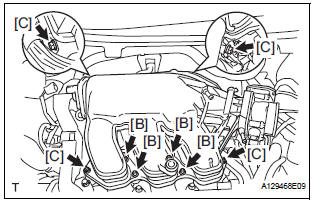
4. INSTALL INTAKE AIR SURGE TANK
NOTICE: DO NOT apply oil to the bolts listed below.

- Install a new gasket to the intake air surge tank [A].
- Using a 5 mm hexagon socket wrench, install the 4
bolts [B].
Torque: 18 N*m (184 kgf*cm, 13 ft.*lbf)
- Install the intake air surge tank with the 2 nuts and 2
bolts [C].
Torque: Nut 16 N*m (163 kgf*cm, 12 ft.*lbf)
Bolt 21 N*m (214 kgf*cm, 15 ft.*lbf)
- Connect the connector [D].
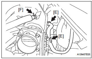
- Connect the union to check valve hose [E].
- Connect the ventilation hose No. 2 [F].
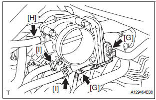
- Install the clamp and connect the throttle with motor body assembly connector [G].
- Connect the vapor feed hose [H].
- Connect the 2 water by-pass hoses to the throttle with motor body assembly [I].
5. INSTALL AIR CLEANER CASE SUB-ASSEMBLY
6. INSTALL AIR CLEANER CAP SUB-ASSEMBLY
7. ADD ENGINE COOLANT
8. INSPECT FOR ENGINE COOLANT LEAK
9. INSPECT FOR FUEL LEAK
10. INSTALL FRONT OUTER COWL TOP PANEL SUBASSEMBLY
11. INSTALL WINDSHIELD WIPER MOTOR ASSEMBLY
12. INSTALL V-BANK COVER SUB-ASSEMBLY
 Inspection
1. KNOCK CONTROL SENSOR
Using an ohmmeter, measure the resistance
between the terminals.
Resistance:
120 to 280 kΩ at 20C (68F)
If the resistance is not specified, replac ...
 EFI relay
Inspection
1. INSPECT EFI RELAY
(a) Using an ohmmeter, measure the resistance
according to the value(s) in the table below.
Standard resistance
If the result is not as specified, replace ...
Other materials:
How to proceed with
troubleshooting
HINT:
Troubleshoot in accordance with the procedures on the
following pages.
1 VEHICLE BROUGHT TO WORKSHOP
2 CUSTOMER PROBLEM ANALYSIS CHECK AND SYMPTOM CHECK
3 INSPECT COMMUNICATION FUNCTION OF LARGE-SCALE MULTIPLEX
COMMUNICATION SYSTEM (BEAN)
Use the intelligent tester to check for norma ...
Diagnosis system
1. CHECK DLC3
The vehicle uses ISO 15765-4 communication
protocol.
The terminal arrangement of the DLC3 complies
with SAE 1962 and matched the ISO 15765-4
format.
If the result is not as specified, the DLC3 may have
a malfunction. Repair or replace the harness and
connecto ...
Rear wheel alignment
ADJUSTMENT
NOTICE:
For vehicles equipped with VSC, if wheel alignment has
been adjusted, and if suspension or underbody
components have been removed/installed or replaced, be
sure to perform the following initialization procedure in
order for the system to function normally:
1. Disconnect the ...
