Toyota Sienna Service Manual: Removal
1. REMOVE ENGINE ASSEMBLY WITH TRANSAXLE
HINT: See page EM-26
2. REMOVE OIL LEVEL GAUGE GUIDE SUBASSEMBLY (See page EM-39) 3. REMOVE NO. 1 OIL PIPE (See page EM-77) 4. REMOVE OIL PIPE (See page EM-77) 5. REMOVE CRANKSHAFT PULLEY (See page EM-79) 6. SEPARATE OIL COOLER PIPE
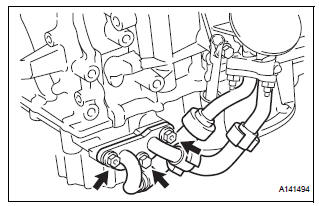
(a) Remove the bolt and 2 nuts, and disconnect the oil cooler pipe from the oil pan sub-assembly.
(b) Remove the gasket from the oil pan sub-assembly.
7. REMOVE WATER INLET HOUSING (See page CO-12) 8. REMOVE CYLINDER HEAD COVER SUB-ASSEMBLY (for Bank 1) (See page EM-82) 9. REMOVE CYLINDER HEAD COVER SUB-ASSEMBLY (for Bank 2) (See page EM-82) 10. REMOVE NO. 2 OIL PAN SUB-ASSEMBLY (See page EM-82) 11. REMOVE OIL STRAINER SUB-ASSEMBLY (See page EM-83) 12. REMOVE OIL PAN SUB-ASSEMBLY (See page EM- 83) 13. REMOVE TIMING CHAIN COVER SUB-ASSEMBLY
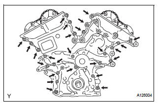
(a) Remove the 23 bolts and 2 nuts as shown in the illustration.
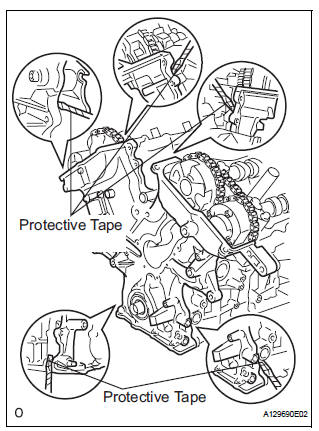
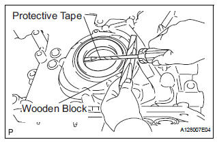
(b) Remove the timing chain cover by prying between the timing chain cover and cylinder head or cylinder block with a screwdriver.
| NOTICE: Be careful not to damage the contact surfaces of the cylinder head, cylinder block and chain cover. |
HINT: Tape the screwdriver tip before use.
(c) Remove the gasket.
14. REMOVE TIMING CHAIN CASE OIL SEAL
(a) Using a screwdriver, pry out the oil seal.
HINT: Tape the screwdriver tip before use.
 Oil pump
Components
...
 Disassembly
1. REMOVE OIL PUMP RELIEF VALVE
(A) using a 27 mm socket wrench, remove the relief
valve plug.
(B) remove the valve spring and oil pump relief valve.
2. REMOVE OIL PUMP COVER
(a) Remove ...
Other materials:
Adjustment
HINT:
On the RH side, use the same procedures as on the LH side.
1. INSPECT SLIDE DOOR PANEL SUB-ASSEMBLY LH
Check that the clearance is within the standard
range.
Standard
2. ADJUST SLIDE DOOR PANEL SUB-ASSEMBLY LH
Using the SST, horizontally and vertically adjust the
do ...
TS and CG Terminal Circuit
DESCRIPTION
The Test Mode (signal check) circuit detects trouble in the sensor or switch
signal, which cannot be
detected by the DTC check.
Connecting terminals TS and CG of the DLC3 starts the check.
WIRING DIAGRAM
INSPECTION PROCEDURE
1 CHECK HARNESS AND CONNECTOR (BETWEEN SKID CONTR ...
Oxygen Sensor Heater Control Circuit Low/ Oxygen Sensor Heater Control
Circuit High/ Oxygen Sensor Heater Circuit Malfunction
DTC P0037 Oxygen Sensor Heater Control Circuit Low
(Bank 1 Sensor 2)
DTC P0038 Oxygen Sensor Heater Control Circuit High
(Bank 1 Sensor 2)
DTC P0057 Oxygen Sensor Heater Control Circuit Low
(Bank 2 Sensor 2)
DTC P0058 Oxygen Sensor Heater Control Circuit High
(Bank 2 Sensor 2)
DTC P0141 Oxyg ...
