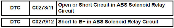
Toyota Sienna Service Manual: Open or Short Circuit in ABS Solenoid Relay Circuit
DESCRIPTION
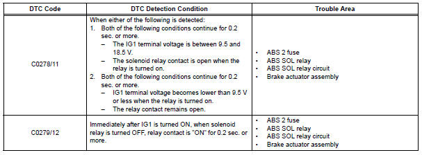
The ABS solenoid relay is built in the brake actuator assembly. This relay supplies power to each ABS solenoid. If the initial check is OK, after the ignition switch is turned to the ON position, the relay goes on.
WIRING DIAGRAM
Refer to DTCs C0226/21, C0236/22, C0246/23 and C0256/24 (See page BC-105).
INSPECTION PROCEDURE
1 INSPECT ABS 2 FUSE
(a) Remove the ABS 2 fuse from the FL block.
(b) Measure the resistance according to the value(s) in the table below.
Standard resistance 

2 INSPECT SKID CONTROL ECU
(a) Disconnect the skid control ECU connector.
(b) Turn the ignition switch to the ON position.
(c) Measure the voltage according to the value(s) in the table below.
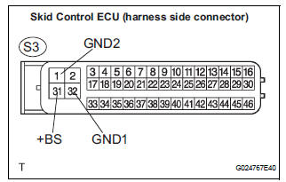
Standard voltage 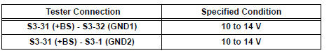

3 RECONFIRM DTC
HINT: This code is detected when a problem is determined in the brake actuator assembly.
The ABS solenoid relay is in the brake actuator assembly.
Therefore, solenoid relay circuit inspection relay unit inspection cannot be performed. Be sure to check if the DTC code is output before replacing the brake actuator assembly.
(a) Clear the DTCs (See page BC-82).
(b) Turn the ignition switch to the ON position.
(c) Are the same DTCs recorded?
Result 
NOTICE: When replacing brake actuator assembly, perform zero point calibration (See page BC-70).
REPLACE BRAKE ACTUATOR ASSEMBLY
4 INSPECT SKID CONTROL ECU (GND TERMINAL)
(a) Disconnect the skid control ECU connector.
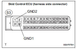
(b) Measure the resistance according to the value(s) in the table below.
Standard resistance 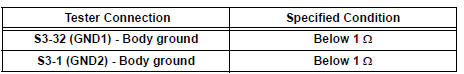

5 RECONFIRM DTC
HINT: This code is detected when a problem is determined in the brake actuator assembly.
The ABS solenoid relay is in the brake actuator assembly.
Therefore, solenoid relay circuit inspection relay unit inspection cannot be performed. Be sure to check if the DTC code is output before replacing the brake actuator assembly.
(a) Clear the DTCs (See page BC-82).
(b) Turn the ignition switch to the ON position.
(c) Are the same DTCs recorded?
Result 
HINT: It is suspected that the DTCs output was caused by the poor connection of the connector terminal.
NOTICE: When replacing brake actuator assembly, perform zero point calibration (See page BC-70).

REPLACE BRAKE ACTUATOR ASSEMBLY
 Open or Short Circuit in ABS Motor Relay Circuit
DESCRIPTION
The ABS motor relay supplies power to the ABS pump motor. While the ABS &
TRAC & VSC are
activated, the ECU switches the ABS motor relay ON and operates the ABS pump
moto ...
 Engine Control System Malfunction
DTC C1201/51 Engine Control System Malfunction
DESCRIPTION
If trouble occurs the engine control system, the ECM transmits the
abnormality to the skid control ECU.
The skid control ECU set this ...
Other materials:
Installation
1. INSTALL FRONT PASSENGER AIRBAG ASSEMBLY
Install the front passenger airbag assembly with the
2 screws.
2. INSTALL INSTRUMENT PANEL SUB-ASSEMBLY
3. CONNECT FRONT PASSENGER AIRBAG ASSEMBLY CONNECTOR
Connect the connector to the front passenger airbag
assembly.
...
Safety Connect services
Automatic Collision Notification
In case of either airbag deployment or severe rear-end collision, the
system is designed to automatically call the response center. The
responding agent receives the vehicle’s location and attempts to
speak with the vehicle occupants to assess the level of emer ...
Removal
1. PRECAUTION
CAUTION:
Be sure to read "PRECAUTION" thoroughly before
servicing.
2. DISCONNECT CABLE FROM NEGATIVE BATTERY
TERMINAL
CAUTION:
Wait for 90 seconds after disconnecting the cable to
prevent the airbag working.
3. REMOVE FRONT SEAT ASSEMBLY (for Manual Seat)
4. REMOVE ...
