Toyota Sienna Service Manual: Removal
1. DISCONNECT CABLE FROM NEGATIVE BATTERY TERMINAL 2. DRAIN ENGINE COOLANT 3. REMOVE FRONT WIPER ARM HEAD CAP (See page WW-4) 4. REMOVE FRONT WIPER ARM RH (See page WW-4) 5. REMOVE FRONT WIPER ARM LH (See page WW-4) 6. REMOVE COWL TOP VENTILATOR LOUVER SUBASSEMBLY (See page WW-4) 7. REMOVE WINDSHIELD WIPER MOTOR AND LINK ASSEMBLY (See page WW-4) 8. REMOVE NO. 1 COWL TOP TO COWL BRACE INNER (See page FU-13) 9. REMOVE COWL TOP PANEL SUB-ASSEMBLY OUTER FRONT (See page FU-13) 10. REMOVE NO. 1 ENGINE UNDER COVER 11. REMOVE V-BANK COVER SUB-ASSEMBLY (See page EM-28) 12. REMOVE AIR CLEANER CAP SUB-ASSEMBLY (See page FU-13) 13. REMOVE INTAKE AIR SURGE TANK ASSEMBLY (See page FU-14) 14. REMOVE NO. 1 SURGE TANK STAY
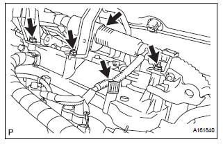
(a) Remove the 2 bolts and nut and disconnect the 2 harness clamps.
(b) Remove the bolt and No. 1 surge tank stay.
15. REMOVE IGNITION COIL ASSEMBLY
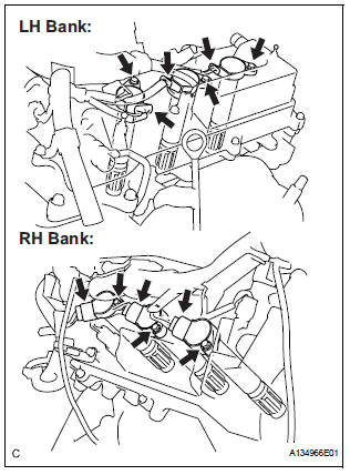
(a) Disconnect the 6 ignition coil connectors.
(b) Remove the 6 bolts and 6 ignition coils.
16. REMOVE SPARK PLUG
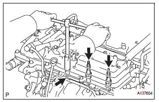
(a) Remove the 6 spark plugs.
 On-vehicle inspection
NOTICE:
In this section, the terms "cold" and "hot" refer to the
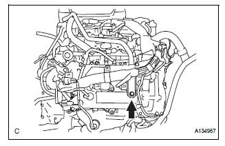
temperature of the coils. "Cold" means approximately -
10°C (14°F) to 50°C (122°F). & ...
 Installation
1. INSTALL SPARK PLUG
(a) Install the 6 spark plugs.
Torque: 18 N*m (183 kgf*cm, 13 ft.*lbf)
2. INSTALL IGNITION COIL ASSEMBLY
(a) Install the 6 ignition coils with the 6 bolts.
Torqu ...
Other materials:
Problem symptoms table
If there are no DTCs output but the problem still occurs,
check the circuits for each problem symptom in the order
given in the table below and proceed to the relevant
troubleshooting page.
NOTICE:
When replacing the brake actuator assembly, sensor,
etc., turn the ignition switch off.
HINT:
...
Customer problem analysis
HINT:
In troubleshooting, confirm that the problem symptoms
have been accurately identified. Preconceptions should be
discarded in order to make an accurate judgment. To
clearly understand what the problem symptoms are, it is
extremely important to ask the customer about the
problem an ...
Removal
1. REMOVE FRONT WHEEL
2. REMOVE FRONT AXLE HUB LH NUT
HINT:
(See page AH-4)
SST 09930-00010
3. SEPARATE SPEED SENSOR FRONT LH
HINT:
(See page AH-4)
4. SEPARATE FRONT DISC BRAKE CALIPER
ASSEMBLY LH
HINT:
(See page AH-4)
5. REMOVE FRONT DISC
6. SEPARATE TIE ROD ASSEMBLY LH
HINT:
(See pa ...
