Toyota Sienna Service Manual: Installation
1. INSTALL SPARK PLUG

(a) Install the 6 spark plugs.
Torque: 18 N*m (183 kgf*cm, 13 ft.*lbf)
2. INSTALL IGNITION COIL ASSEMBLY
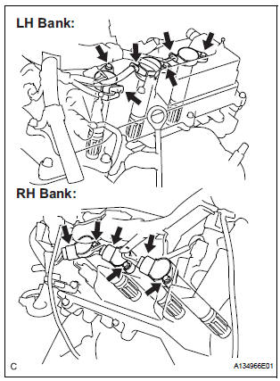
(a) Install the 6 ignition coils with the 6 bolts.
Torque: 10 N*m (102 kgf*cm, 7 ft.*lbf) (b) Connect the 6 ignition coil connectors.
3. INSTALL NO. 1 SURGE TANK STAY
NOTICE:
DO NOT apply oil to the bolt listed below:
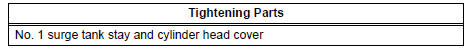 |
(a) Install the No. 1 surge tank stay with the bolt.
Torque: 21 N*m (214 kgf*cm, 15 ft.*lbf)
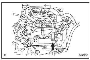
(b) Install the 2 bolts, 2 clamps, and nut.
Torque: 8.3 N*m (84 kgf*cm, 73 in.*lbf)
4. INSTALL INTAKE AIR SURGE TANK ASSEMBLY (See page FU-19) 5. INSTALL AIR CLEANER CAP SUB-ASSEMBLY (See page FU-20) 6. ADD ENGINE COOLANT (See page CO-7) 7. CONNECT CABLE TO NEGATIVE BATTERY TERMINAL 8. INSPECT FOR ENGINE COOLANT LEAK (See page CO-1) 9. INSTALL V-BANK COVER SUB-ASSEMBLY (See page EM-63) 10. INSTALL COWL TOP PANEL SUB-ASSEMBLY OUTER FRONT (See page FU-21) 11. INSTALL NO. 1 COWL TOP TO COWL BRACE INNER (See page FU-21)
12. INSTALL WINDSHIELD WIPER MOTOR AND LINK ASSEMBLY (See page WW-6)
13. INSTALL FRONT WIPER ARM LH (See page WW-6)
14. INSTALL FRONT WIPER ARM RH (See page WW-7)
 Removal
1. DISCONNECT CABLE FROM NEGATIVE BATTERY
TERMINAL
2. DRAIN ENGINE COOLANT
3. REMOVE FRONT WIPER ARM HEAD CAP (See page
WW-4)
4. REMOVE FRONT WIPER ARM RH (See page WW-4)
5. REMOVE FRONT WIPER A ...
 2Gr-fe starting
...
Other materials:
Terminals of ECU
1. TELEVISION CAMERA ASSEMBLY
Disconnect the T10 camera connector
Measure the voltage and resistance of each
terminal of the wire harness side connector.
If the result is not as specified, there may be a
malfunction on the wire harness side.
Reconnect the T10 ...
Rear axle hub bolt
COMPONENTS
Replacement
HINT:
Replace the RH side using the same procedures as for the
LH side.
1. REMOVE REAR WHEEL
2. SEPARATE REAR DISC BRAKE CALIPER
ASSEMBLY LH
(a) Separate rear disc brake caliper assembly LH for
2WD and disk rear brake type (See page AH-16).
3. SEPARATE REAR D ...
Road test
1. PROBLEM SYMPTOM CONFIRMATION
HINT:
The dynamic laser cruise control system has two cruise
control modes: the constant speed control mode and
vehicle-to-vehicle distance control mode.
The vehicle-to-vehicle distance control mode is
always selected when starting up the dynamic laser ...
