Toyota Sienna Service Manual: Removal
1. Disconnect cable from negative battery terminal
2. REMOVE STEERING COLUMN COVER LOWER
(A) insert the key into the ignition key cylinder and release the steering lock.
(B) turn the steering wheel clockwise to gain access to the screw and remove the screw.
(c) Turn the steering wheel counterclockwise to gain access to the screw and remove the screw.
(d) Detach the 4 claws, and remove the steering column cover lower.
3. REMOVE IGNITION SWITCH ASSEMBLY
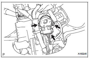
(a) Disconnect the ignition switch connector.
(b) Remove the 2 screws and ignition switch.
 Ignition switch
Components
...
 Inspection
1. Inspect ignition switch assembly
(a) Measure the resistance of the switch.
Standard resistance
If the result is not as specified, replace the switch
assembly. ...
Other materials:
Folding Motor Circuit
DESCRIPTION
The fold seat control ECU receives a switch operation signal from the fold
seat switch and activates the
folding motor. At this time, the Hall IC (seat cushion position sensor) detects
the actuation signal. The fold
seat control ECU uses signals from the Hall IC (seat cushion posi ...
Reassembly
1. INSTALL LH REAR BUMPER SIDE RETAINER
Install the LH rear bumper side retainer with the 3
screws.
2. INSTALL RH REAR BUMPER SIDE RETAINER
Install the RH rear bumper side retainer with the 3
screws.
3. INSTALL REAR BUMPER REINFORCEMENT SUBASSEMBLY
Install the rear bumper reinf ...
Manual Up / Down Function does not Operate on Rear RH Only
DESCRIPTION
If the manual UP/DOWN function does not operate, the power window motor, the
regulator switch or the
wire harness may be malfunctioning.
WIRING DIAGRAM
INSPECTION PROCEDURE
1 CHECK WIRE HARNESS (POWER SOURCE)
Disconnect the P39 regulator switch connector.
Turn ...
