Toyota Sienna Service Manual: Registration
1. DESCRIPTION OF CODE REGISTRATION
HINT: The key has 2 codes: The key code (immobiliser code) and the wireless code. Both of these codes need to be registered. Refer to page for the wireless code registration procedures.
- When adding master keys or sub keys (Additional registration):
- Register key code (immobiliser code) in the transponder key ECU.

- When replacing the transponder key ECU (New registration):
- Register the key code (immobiliser code) in the transponder key ECU.

- Register the ECU COMMUNICATION ID between the ECM and the transponder key ECU.

- When replacing the ECM:
- Register the ECU COMMUNICATION ID between the ECM and the transponder key ECU.

2. KEY REGISTRATION
- Automatic registration (Procedure "B") The new registration of the key codes (immobiliser codes) is made automatically.
HINT:
- When installing a new transponder key ECU, the key codes (immobiliser codes) must be registered.
- A new transponder key ECU starts in the automatic key code registration mode. In this mode, a maximum of 4 key codes for 3 master keys and 1 sub key can be registered. Since the transponder key ECU can distinguish types of keys, any registration order is acceptable.
Automatic Key Code Registration (New Registration)

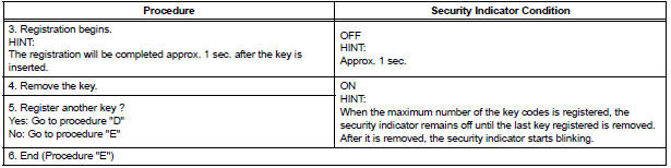
HINT:
- When no key is inserted in the key cylinder while the system is in automatic key code registration mode, the security indicator remains on.
- When the immobiliser system is operating normally and the key is pulled out, the security indicator blinks continuously.
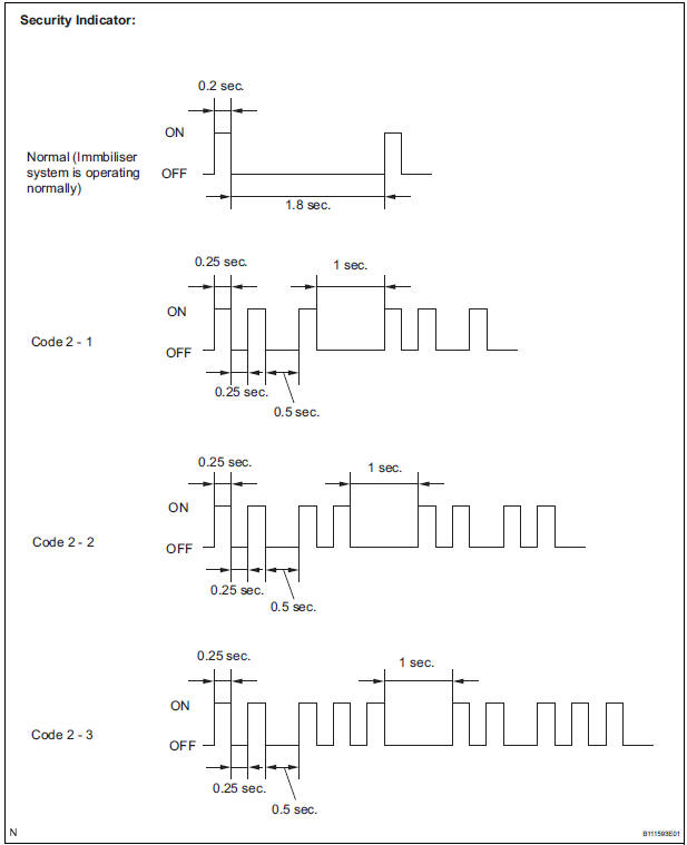
- If the key code registration has failed in the automatic key code registration mode, code 2-1 will be output from the security indicator. Trying to register an already registered key will cause code 2-2 to be output when the key is inserted. If the number of registered key codes exceeds the limit, code 2-3 will be output from the security indicator. The output details are shown below.
- Finish the automatic key code registration mode.
The automatic key code registration mode can be forced to end, when at least 1 key code (immobiliser code) for the master key has been registered.
- Turn the ignition switch on and off 5 times within 10 seconds using the already registered master key.
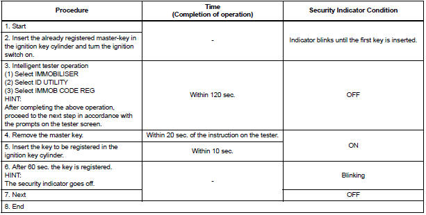
3. REGISTRATION OF ADDITIONAL KEY
- Additional registration (Procedure "A") Register an additional key by using the intelligent tester.
HINT:
- A maximum of 5 key codes and 3 sub key codes can be registered.
- Registration mode will end if any step is not completed within the specified time.
- When the ignition cylinder or the key cylinder set is replaced, remove the transmitter module from the original master key. Then install this transmitter module to a new key and use it as master key. If necessary, use this master key to register other keys.
NOTICE: When only the ignition key cylinder has been replaced, you can lock or unlock doors by wireless operation using the new key with built in transmitter but not by inserting it in the door key cylinder. Therefore, keep the original key for door lock or unlock operation in order to avoid malfunctions caused by a dead transmitter battery in the new key.
Additional Registration
NOTICE: If the key code registration has failed in automatic key code registration mode, code 2-1 will be output from the security indicator. Trying to register an already registered key will cause code 2-2 to be output when the key is inserted. If the number of registered key codes exceeds the limit, code 2-3 will be output from the security indicator. The output details are shown in procedure "B".
HINT:
- A brief outline of procedures for key code registration is shown above. For detailed information, please refer to the screen of the intelligent tester.
- When the immobiliser system is operating normally and the key is pulled out, the security indicator will blink.
4. ERASURE OF KEY CODE
- Erase key codes by using the intelligent tester.
HINT:
- All key codes will be erased except for the master-key which is used for erasing the key codes. In order to use a key for which the code has been erased, it is necessary to register the key code again.
- The registration operation will be cancelled if any step is not completed within the specified time.
Erasing Key Code

HINT:
- A brief outline of procedures for key code registration is shown above. For detailed information, please refer to the screen of the intelligent tester.
- When the immobiliser system is operating normally and the key is pulled out, the security indicator will blink
5. ECU COMMUNICATION ID REGISTRATION
NOTICE:
- The ECU communication ID should be registered when the transponder key ECU and/or the ECM is replaced in order to match it to the ECM COMMUNICATION ID.
- The SFI system cannot be started unless the ECM COMMUNICATION ID matches.
- ECU communication ID registration (Procedure "C") Register the ECU COMMUNICATION ID, after the transponder key ECU and/or the ECM is replaced turn the ignition switch on.
- Using SST, connect terminals TC and CG of
the DLC3.
SST 09843-18040
- Turn the ignition on and leave it as is for 30 minutes.
- Check that the engine starts.
 How to proceed with
troubleshooting
How to proceed with
troubleshooting
HINT:
Use this procedure to troubleshoot the engine immobiliser
system.
The intelligent tester should be used in steps 4, 5 and 7.
1 VEHICLE BROUGHT TO WORKSHOP
2 CUSTOMER PROB ...
 Problem symptoms table
ENGINE IMMOBILISER SYSTEM
...
Other materials:
Reassembly
1. INSTALL OIL PUMP COVER
(a) Coat the drive and driven rotors with engine oil and
place them into the timing chain cover with the
marks facing outward (oil pump cover side). Check
that the rotors rotate smoothly.
(b) Install the oil pump cover with the 8 bolts.
Torque: 9.1 N*m (93 kgf ...
ABS Control System Malfunction
DTC 43 ABS Control System Malfunction
DESCRIPTION
This DTC is output when the VSC system detects a malfunction in the ABS
control system.
INSPECTION PROCEDURE
NOTICE:
When replacing the brake actuator assembly, perform zero point calibration
(See page BC-70).
1 CHECK ABS CONTROL SYSTEM
( ...
Rear speaker
COMPONENTS
ON-VEHICLE INSPECTION
1. INSPECT REAR SPEAKER
HINT:
Remove interior parts so that the rear speaker can be
seen.
Check the speaker installation.
OK:
The speaker is securely installed.
If the result is not as specified, reinstall the rear
speaker.
Vi ...
