Toyota Sienna Service Manual: Removal
1. DISCONNECT BATTERY NEGATIVE TERMINAL 2. REMOVE FRONT DOOR SCUFF PLATE LH HINT: (See page IP-6) 3. REMOVE FRONT DOOR SCUFF PLATE RH HINT: (See page IP-6) 4. REMOVE COWL SIDE TRIM BOARD LH HINT: (See page IP-6) 5. REMOVE COWL SIDE TRIM BOARD RH HINT: (See page IP-6) 6. REMOVE INSTRUMENT PANEL FINISH PANEL SUBASSEMBLY LOWER LH HINT: (See page IP-6) 7. REMOVE GLOVE COMPARTMENT DOOR STOPPER SUB-ASSEMBLY HINT: (See page IP-7) 8. REMOVE GLOVE COMPARTMENT DOOR ASSEMBLY HINT: (See page IP-7) 9. REMOVE FLOOR CARPET COVER CENTER LH HINT: (See page IP-8) 10. REMOVE FLOOR CARPET COVER CENTER RH HINT: (See page IP-8) 11. REMOVE INSTRUMENT CLUSTER FINISH PANEL CENTER NO.1 HINT: (See page IP-8) 12. REMOVE INSTRUMENT CLUSTER FINISH PANEL CENTER NO.2 HINT: (See page IP-8)
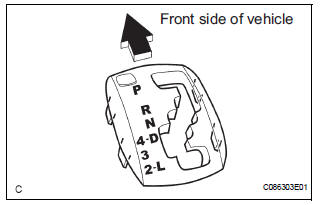
13. REMOVE SHIFT LEVER KNOB SUB-ASSEMBLY
(a) Remove the floor shift lever knob sub-assembly.
14. REMOVE POSITION INDICATOR HOUSING ASSEMBLY
(a) Using a screwdriver, remove the position indicator housing assembly from the instrument cluster finish panel assembly center.
15. REMOVE INSTRUMENT CLUSTER FINISH PANEL ASSEMBLY CENTER
HINT: (See page IP-9)
16. REMOVE SHIFT LEVER CAP
(a) Using a small screwdriver, remove the shift lever cap from the position indicator housing assembly.
17. REMOVE INSTRUMENT CLUSTER FINISH PANEL SUB-ASSEMBLY LOWER CENTER
HINT: (See page IP-9)
18. DISCONNECT TRANSMISSION CONTROL CABLE ASSEMBLY
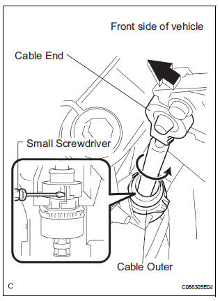
(a) Using a screwdriver, disconnect the cable end from the shift lever assembly.
(b) Using a small screwdriver, disconnect the outer of transmission control cable assembly from the shift lever assembly.
19. REMOVE SHIFT LEVER ASSEMBLY
(a) Disconnect the 2 connectors.
(b) Remove the 4 bolts and disconnect the shift lever assembly from the vehicle.
 Shift lever
Components
...
 Disassembly
1. REMOVE INDICATOR LIGHT WIRE SUB-ASSEMBLY
(a) Remove the indicator light wire sub assembly from
the position indicator light guide.
2. REMOVE POSITION INDICATOR LIGHT BULB
(a) Remove the shi ...
Other materials:
Random / Multiple Cylinder Misfire Detected/ Cylinder Misfire Detected
DTC P0300 Random / Multiple Cylinder Misfire Detected
DTC P0301 Cylinder 1 Misfire Detected
DTC P0302 Cylinder 2 Misfire Detected
DTC P0303 Cylinder 3 Misfire Detected
DTC P0304 Cylinder 4 Misfire Detected
DTC P0305 Cylinder 5 Misfire Detected
DTC P0306 Cylinder 6 Misfire Detected
DESCRIPTION ...
Initialization
NOTICE:
Resetting the power window motor (initializing the
pulse sensor) is necessary when the battery terminal
is disconnected; when the master switch, wire
harness, power window regulator and power window
motor are replaced or removed/installed; or when the
fuses are replaced. ...
Installation with LATCH system (second seat)
Fold the seatback while pulling
the lever and move to the rearmost
recline position.
Widen the gap between the seat cushion and seatback slightly.
Type A
Latch the hooks of the lower
straps onto the LATCH
anchors. If the child restraint
has a top tether strap, the ...
