Toyota Sienna Service Manual: Crankshaft Position - Camshaft Position Correlation
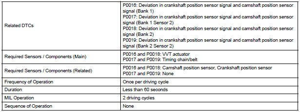
DTC P0016 Crankshaft Position - Camshaft Position Correlation (Bank 1 Sensor A)
DTC P0017 Crankshaft Position - Camshaft Position Correlation (Bank 1 Sensor B)
DTC P0018 Crankshaft Position - Camshaft Position Correlation (Bank 2 Sensor A)
DTC P0019 Crankshaft Position - Camshaft Position Correlation (Bank 2 Sensor B)
DESCRIPTION
Refer to DTC P0335
|
DTC No. |
DTC Detection Condition |
Trouble Area |
| P0016 | Deviations in crankshaft and camshaft position sensor (for intake camshaft) 1 signals (2 trip detection logic) |
|
| P0017 | Deviations in crankshaft and camshaft position sensor (for exhaust camshaft) 1 signals (2 trip detection logic) | |
| P0018 | Deviations in crankshaft and camshaft position sensor (for intake camshaft) 2 signals (2 trip detection logic) | |
| P0019 | Deviations in crankshaft and camshaft position sensor (for exhaust camshaft) 2 signals (2 trip detection logic) |
MONITOR DESCRIPTION
DTC P0016 and P0018
The ECM optimizes the valve timing by using the VVT (Variable Valve Timing)
system to control the intake
camshaft. The VVT system includes the ECM, the Oil Control Valve (OCV) and the
VVT controller.
The ECM sends a target duty-cycle control signal to the OCV. This control signal regulates the oil pressure applied to the VVT controller. The VVT controller can advance or retard the intake camshaft. The ECM calibrates the intake valve timing by setting the intake camshaft to the most retarded angle while the engine is idling. The ECM closes the OCV to retard the cam. The ECM stores this value as the VVT learning value. When the difference between the target and actual intake valve timings is 5 CA (Crankshaft Angle) or less, the ECM stores it.
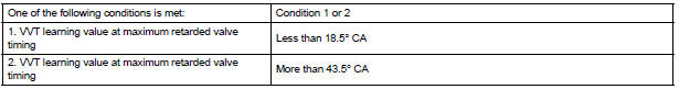
If the VVT learning value matches the following conditions, the ECM determines the existence of a malfunction in the VVT system, and sets the DTC.
- The VVT learning value: Less than 18.5 CA, or more than 43.5 CA.
- The above condition continues for 18 seconds or more.
This DTC indicates that the intake camshaft has been installed toward the crankshaft at an incorrect angle, caused by factors such as the timing chain having jumped a tooth.
This monitor begins to run after the engine has idled for 5 minutes.
DTC P0017 and P0019
The ECM checks valve timing (VVT learning value) on the exhaust side while the
engine is running at a
low speed, in order to monitor the gap between current and target valve timings
on the exhaust side. The
VVT learning value is calculated from the positions of the camshaft and
crankshaft. The camshaft will
come to the most retarded position when the engine is running at a low speed. If
the camshaft position is
normal, the VVT learning value should be within the specified range. If the VVT
learning value is not within
the specified range, the ECM determines this as a malfunction.
MONITOR STRATEGY
TYPICAL ENABLING CONDITIONS
All:

P0016 and P0018:

P0017 and P0019:

TYPICAL MALFUNCTION THRESHOLDS
P0016 and P0018:
P0017 and P0019:

WIRING DIAGRAM
Refer to DTC P0335
INSPECTION PROCEDURE
HINT: Read freeze frame data using the intelligent tester. The ECM records vehicle and driving condition information as freeze frame data the moment a DTC is stored. When troubleshooting, freeze frame data can be helpful in determining whether the vehicle was running or stopped, whether the engine was warmed up or not, whether the air-fuel ratio was lean or rich, as well as other data recorded at the time of a malfunction
1 CHECK VALVE TIMING (CHECK FOR LOOSE AND A JUMPED TOOTH OF TIMING CHAIN)
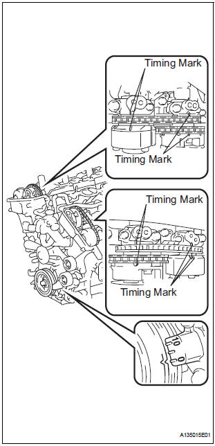
- Remove the cylinder head covers RH and LH.
- Turn the crankshaft to align the matchmarks of the crankshaft.
- Align the notch of the crankshaft pulley to the "0" position.
- Check if the matchmarks of the camshaft pulley and camshaft bearing cap align.
- Turn the crankshaft clockwise by 360 if the matchmarks do not align. Check if they align once again.
OK: The matchmarks of the camshaft pulley and the camshaft bearing cap align when the notch of the crankshaft pulley is in the "0" position.
NOTICE: After replacing the ECM or adjusting intake valve timing, confirm that the DTC output does not recur.
- Confirm that the DTC output does not recur.
- Connect the intelligent tester to the DLC3.
- Turn the ignition switch to the ON position.
- Turn the tester on.
- Clear the DTCs.
- Select the check mode using the tester.
- Start the engine and warm it up.
- Allow the engine to idle for 1 minute or more, and then drive the vehicle for 1 minute or more.
- Confirm that no DTC is set using the tester.
REPLACE ECM
 Camshaft Position "B" - Timing Over-Advanced
DTC P0014 Camshaft Position "B" - Timing Over-Advanced
or System Performance (Bank 1)
DTC P0015 Camshaft Position "B" - Timing Over-Retarded
(Bank 1)
DTC P0024 Camshaft Positio ...
 Oxygen (A/F) Sensor Heater Control Circuit
Low/ Oxygen (A/F) Sensor Heater Control Circuit
High
Oxygen (A/F) Sensor Heater Control Circuit
Low/ Oxygen (A/F) Sensor Heater Control Circuit
High
DTC P0031 Oxygen (A/F) Sensor Heater Control Circuit
Low (Bank 1 Sensor 1)
DTC P0032 Oxygen (A/F) Sensor Heater Control Circuit
High (Bank 1 Sensor 1)
DTC P0051 Oxygen (A/F) Sensor Heater Control ...
Other materials:
TC and CG Terminal Circuit
DESCRIPTION
DTC output mode is set by connecting terminals 13 (TC) and 4 (CG) of the
DLC3. The DTCs are indicated
by blinks of the tire pressure warning light.
WIRING DIAGRAM
HINT:
When each warning light blinks continuously, a ground short in the wiring of
terminal TC of the DLC3 or an ...
Removal
1. PRECAUTION
HINT:
See page RS-1
2. DISCONNECT BATTERY NEGATIVE TERMINAL
Wait for 90 seconds after disconnecting the battery
terminal to prevent the airbag working.
3. PLACE FRONT WHEELS FACING STRAIGHT AHEAD
4. REMOVE STEERING WHEEL COVER LOWER NO.2
(See page RS-424)
5. REMOVE STEERING WH ...
Installation
1. INSTALL BRAKE PEDAL SUPPORT ASSEMBLY
(a) Install the brake pedal support sub-assembly with
the 4 nuts.
Torque: 16 N*m (160 kgf*cm, 12 ft.*lbf)
(b) Install the clip and clevis pin to the brake pedal
lever.
(c) Using needle-nose pliers, install the tension spring.
(d) Install the ...
