Toyota Sienna Service Manual: Room Temperature Sensor Circuit
DESCRIPTION
This sensor detects the cabin temperature that is used as the basis for
temperature control and sends a
signal to the A/C amplifier. 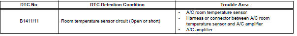
WIRING DIAGRAM 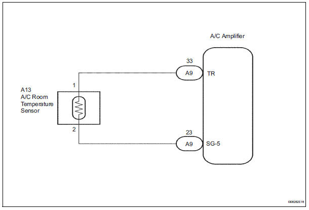
INSPECTION PROCEDURE
1 READ VALUE OF INTELLIGENT TESTER
(a) Connect the intelligent tester to the DLC3.
(b) Turn the ignition switch to the ON position and turn the intelligent tester main switch on.
(c) Select the item below in the DATA LIST, and read the display on the intelligent tester.
DATA LIST / AIR CONDITIONER: 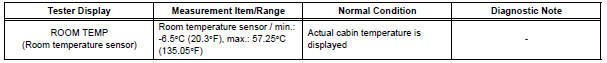
OK: The display is as specified in the normal condition column.
Result 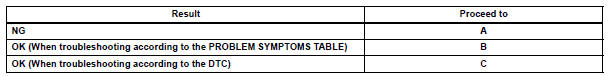

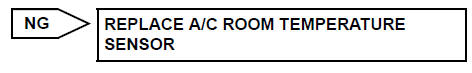
2 INSPECT A/C ROOM TEMPERATURE SENSOR
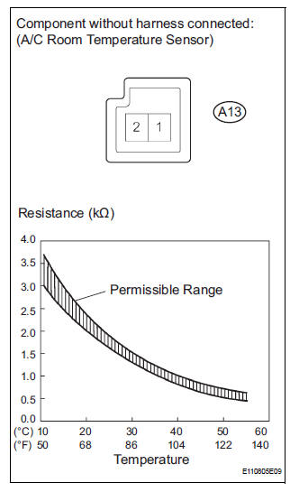
(a) Remove the A/C room temperature sensor.
(b) Measure the resistance according to the value(s) in the table below.
Standard resistance 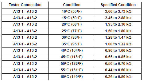
NOTICE:
- Hold the sensor only by its connector. Touching the sensor may change the resistance value.
- When measuring, the sensor temperature must be the same as the room temperature.
HINT: As the temperature increases, the resistance decreases (see the graph).

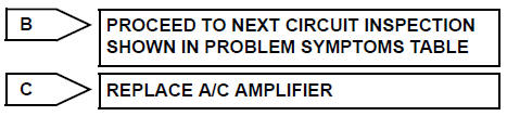
3 CHECK HARNESS AND CONNECTOR (A/C ROOM TEMPERATURE SENSOR - A/C AMPLIFIER)
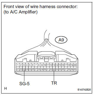
(a) Disconnect the connector from the A/C amplifier.
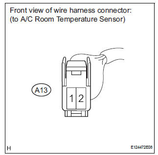
(b) Disconnect the connector from the A/C room temperature sensor.
(c) Measure the resistance according to the value(s) in the table below.
Standard resistance 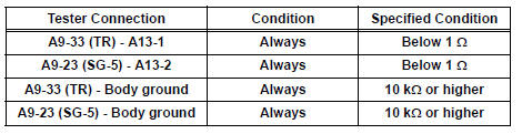

REPLACE A/C AMPLIFIER
 Actuator check
1. ACTUATOR CHECK
(a) After entering the DTC check mode (Sensor Check
Mode), press the R/F switch.
(b) As each damper, motor and relay automatically
operate actuator check at 1-second interval ...
 Ambient temperature sensor circuit
DTC B1412/12 Ambient Temperature Sensor Circuit
DESCRIPTION
The ambient temperature sensor is installed in front of the condenser to
detect the ambient temperature
which is used to control the ai ...
Other materials:
Disc cannot be Played/ No Playable Files/ Copyright Protection Error
DTC 44-7D Disc cannot be Played
DTC 44-7E No Playable Files
DTC 44-7F Copyright Protection Error
DESCRIPTION
DTC No.
DTC Detecting Condition
Trouble Area
44-7D
An incompatible MP3/WMA file is used.
Although the file has an extension of ".mp3 ...
Installation
1. INSTALL REAR AXLE HUB & BEARING ASSEMBLY LH
(a) Install the hub & bearing assembly LH with the 4
bolts.
Torque: 56 N*m (571 kgf*cm, 41 ft.*lbf)
2. INSPECT BEARING BACKLASH (See page AH-19)
3. INSPECT AXLE HUB DEVIATION (See page AH-19)
4. INSTALL REAR DRIVE SHAFT ASSEMBLY LH (Se ...
Installation
1. INSTALL REAR AXLE BEAM DAMPER
(a) Install the rear axle beam damper to the rear axle
beam assembly.
2. INSTALL REAR AXLE CARRIER BUSH LH
(a) Align the matchmarks on the axle beam assembly
with the 2 notches of a new bushing and temporarily
install the bushing to the rear axle beam assem ...
