Toyota Sienna Service Manual: Power Slide Door Warning Buzzer LH does not Sound
DESCRIPTION
- The power slide door system uses warning buzzers built into LH slide doors respectively. Each buzzer has 2 ways of sounding that are used differently according to the situations.
- When all the following conditions are met, the warning buzzer sounds at a cycle of 0.3 seconds:
* The ignition switch is turned ON.
* The shift lever is moved into any position except P position.
* The slide door is open or the power slide door is activated to open.
The warning buzzer continues to sound until the slide door is fully closed or the shift lever is moved into the P position.
- While the power slide door is operating, the warning buzzer that notifies that the door is moving sounds at a cycle of 0.7 seconds. This stops sounding when the power slide door stops. This way of sounding is set to OFF at factory (default setting) and can be customized when required.
- The power slide door ECU LH directly sends a signal to the warning buzzer.
HINT:
- Only item 2 can be customized.
- If both items occur at the same time, item 1 is prior to the other.
WIRING DIAGRAM
INSPECTION PROCEDURE
1 PERFORM ACTIVE TEST BY INTELLIGENT TESTER
- Select the ACTIVE TEST and then check that the power slide door warning buzzer LH operates.
HINT: During the ACTIVE TEST, the intelligent tester sends a signal to the power slide door ECU LH to activate the warning buzzer. If the warning buzzer is activated, the warning buzzer itself and the wire harness between the warning buzzer and power slide door ECU LH are considered to be functioning normally
OK (Power slide door ECU LH):

2 CHECK WIRE HARNESS (POWER SLIDE DOOR WARNING BUZZER LH - BODY GROUND)
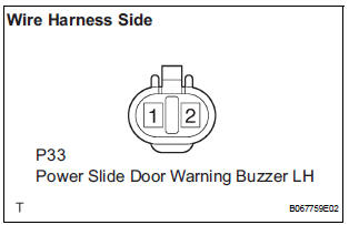
- Remove the buzzer connector.
- Inspect the buzzer connector side voltage.
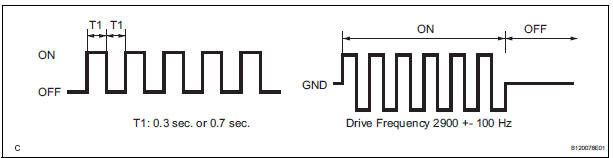
NOTICE: Use an oscilloscope to check the output voltages of the buzzer.
Voltage

3 INSPECT POWER SLIDE DOOR WARNING BUZZER LH
- Check the resistance of the buzzer.
Resistance
NOTICE:
- The circuit that causes the buzzer to sounds is built into the slide door ECU, not around the buzzer.
- Directly applying battery voltage to the buzzer does not cause the buzzer to sound.
4 CHECK WIRE HARNESS (POWER SLIDE DOOR WARNING BUZZER LH - POWER SLIDE DOOR ECU LH)
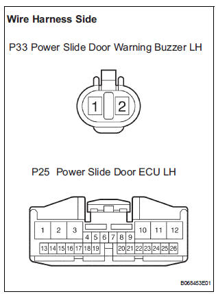
- Disconnect the P33 buzzer and the P25 ECU connectors.
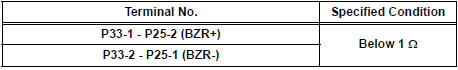
- Check the resistance between the wire harness side connectors.
Resistance (Check for open circuit)
REPLACE POWER SLIDE DOOR ECU LH
 Power Slide Door does not Fully Open
DESCRIPTION
When the LH / RH rear window is open 105 mm (5.91 in.) or more,
the slide door half-open stopper is
activated to force the slide door to stop at approximately 105 mm (5.91 i ...
 Power Slide Door Warning Buzzer RH does not Sound
DESCRIPTION
The power slide door system uses warning buzzers built into RH
slide doors respectively. Each buzzer
has 2 ways of sounding that are used differently according to the
sit ...
Other materials:
On-vehicle inspection
1. FRONT SEAT SIDE AIRBAG ASSEMBLY (VEHICLE
NOT INVOLVED IN COLLISION)
Perform a diagnostic system check.
With the front seat side airbag assembly installed on
the vehicle, perform a visual check. If there are any
defects as mentioned below, replace the front
seatback as ...
Back-up light assembly
COMPONENTS
REMOVAL
1. REMOVE BACK DOOR GARNISH CENTER
2. REMOVE BACK DOOR SIDE GARNISH LH
3. REMOVE BACK DOOR SIDE GARNISH RH
4. REMOVE BACK DOOR STRAP COVER SUBASSEMBLY
5. REMOVE BACK DOOR PULL STRAP
6. REMOVE BACK DOOR TRIM BOARD ASSEMBLY
7. REMOVE BACK-UP LIGHT ASSEMBLY
&n ...
Reassembly
1. Install position indicator slide cover
(a) Install the position indicator slide cover No.2 to the
position indicator slide cover.
2. INSTALL POSITION INDICATOR SLIDE COVER
(a) Install the position indicator slide cover to the shift
lever assembly.
(b) Install the shift lever slide cov ...
