Toyota Sienna Service Manual: Ambient temperature sensor circuit
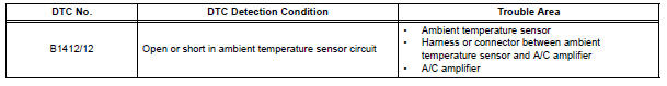
DTC B1412/12 Ambient Temperature Sensor Circuit
DESCRIPTION
The ambient temperature sensor is installed in front of the condenser to detect the ambient temperature which is used to control the air conditioner "AUTO" mode. This sensor is connected to the A/C amplifier and detects fluctuations in the ambient temperature. This data is used for controlling the cabin temperature. The sensor sends a signal to the A/C amplifier. The resistance of the ambient temperature sensor changes in accordance with the ambient temperature. As the temperature decreases, the resistance increases. As the temperature increases, the resistance decreases.
The A/C amplifier applies voltage (5 V) to the ambient temperature sensor and
reads voltage changes as
the resistance of the ambient temperature sensor changes.
WIRING DIAGRAM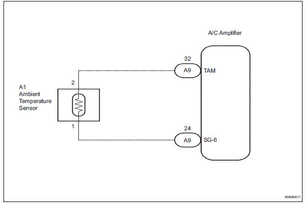
INSPECTION PROCEDURE
1 READ VALUE OF INTELLIGENT TESTER
(a) Connect the intelligent tester to the DLC3.
(b) Turn the ignition switch to the ON position and turn the intelligent tester main switch on.
(c) Select the item below in the DATA LIST, and read the display on the intelligent tester.
DATA LIST / AIR CONDITIONER: 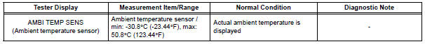
OK: The display is as specified in the normal condition column.
Result 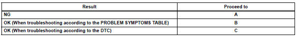

2 INSPECT AMBIENT TEMPERATURE SENSOR
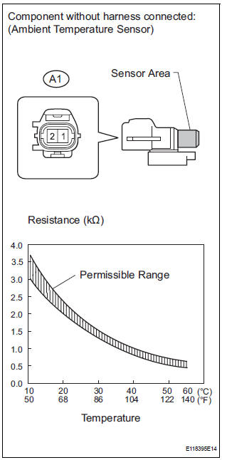
(a) Remove the ambient temperature sensor.
(b) Measure the resistance according to the value(s) in the table below.
Standard resistance 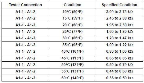
NOTICE:
- Even slightly touching the sensor may change the resistance value. Be sure to hold the connector of the sensor.
- When measuring, the sensor temperature must be the same as the ambient temperature.
HINT: As the temperature increases, the resistance decreases (see the graph).

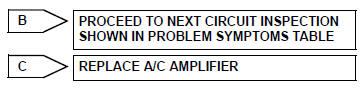
3 CHECK HARNESS AND CONNECTOR (AMBIENT TEMPERATURE SENSOR - A/C AMPLIFIER)
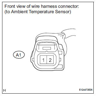
(a) Disconnect the ambient temperature sensor connector.
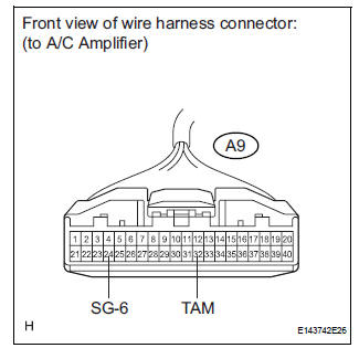
(b) Disconnect the A/C amplifier connector.
(c) Measure the resistance according to the value(s) in the table below.
Standard resistance 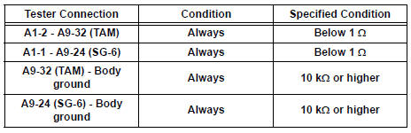

REPLACE A/C AMPLIFIER
 Room Temperature Sensor Circuit
DESCRIPTION
This sensor detects the cabin temperature that is used as the basis for
temperature control and sends a
signal to the A/C amplifier.
WIRING DIAGRAM
INSPECTION PROCEDURE
1 READ VAL ...
 Evaporator temperature sensor circuit
DESCRIPTION
The evaporator temperature sensor (A/C thermistor) is installed on the
evaporator in the air conditioning
unit. It detects the temperature of the cooled air that has passed through the ...
Other materials:
Armrests
Pull the armrest down for use.
Front seat
Second seat (if equipped)
Adjusting the front seat armrests (if equipped)
Push the armrest down while pressing the
button.
NOTICE
To prevent damage to the armrest, do not apply too much load on the
armrest.
...
Inspection
1. INSPECT SPIDER BEARING
(a) Check that the spider bearing moves smoothly by
turning the flange.
(b) Check for the looseness around the joint by strongly
moving the flange in the axial and radial directions.
HINT:
If necessary, replace the shaft.
2. INSPECT INTERMEDIATE SHAFT
(a) Usin ...
Problem symptoms table
POWER WINDOW CONTROL SYSTEM (W/ JAM PROTECTION)
Symptom
Suspected Area
AUTO UP/DOWN function does not operate
Power window regulator motor assembly (Driver side)
Wire harness
Power window regulator master switch assembly
Remote ...
