Toyota Sienna Service Manual: Seat Belt Buckle Switch LH Circuit Malfunction
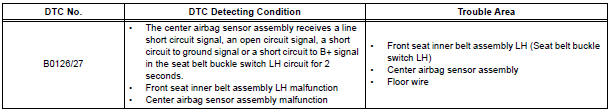
DTC B0126/27 Seat Belt Buckle Switch LH Circuit Malfunction
DESCRIPTION
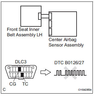
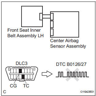
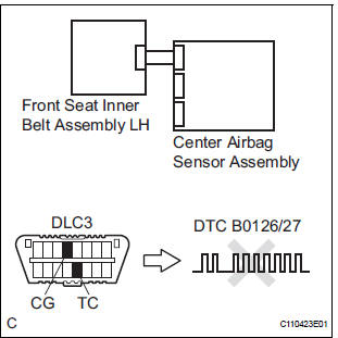
The seat belt buckle switch LH circuit consists of the center airbag sensor assembly and the front seat inner belt assembly LH.
DTC B0126/27 is recorded when a malfunction is detected in the seat belt buckle switch LH circuit
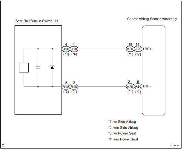
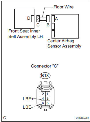
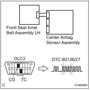
WIRING DIAGRAM
INSPECTION PROCEDURE
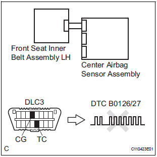
1 CHECK DTC
- Turn the ignition switch to the ON position, and wait for at least 60 seconds.
- Clear the DTCs stored in memory.
- Turn the ignition switch to the LOCK position.
- Turn the ignition switch to the ON position, and wait for at least 60 seconds.
- Check the DTCs.
OK: DTC B0126/27 is not output.
HINT: Codes other than code B0126/27 may be output at this time, but they are not related to this check.
USE SIMULATION METHOD TO CHECK
2 CHECK CONNECTION OF CONNECTORS
- Turn the ignition switch to the LOCK position.
- Disconnect the negative (-) terminal cable from the battery, and wait for at least 90 seconds.
- Check that the connectors are properly connected to the center airbag sensor assembly and the front seat inner belt assembly LH.
OK: The connectors are connected.
3 CHECK VEHICLE
- Check the front driver seat type.
Result

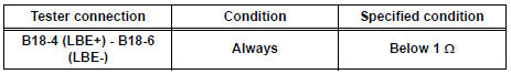
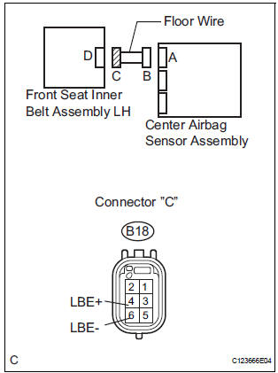
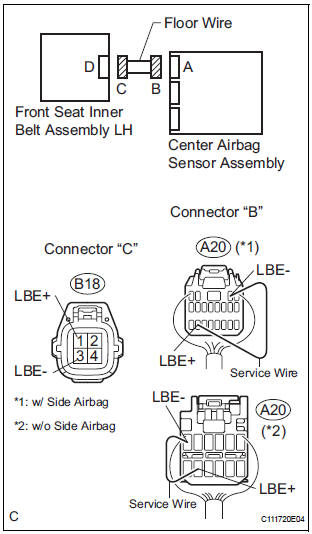
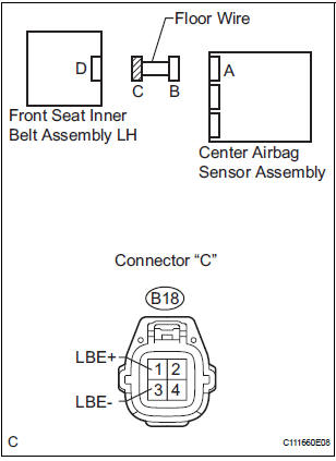
4 CHECK FLOOR WIRE (OPEN)
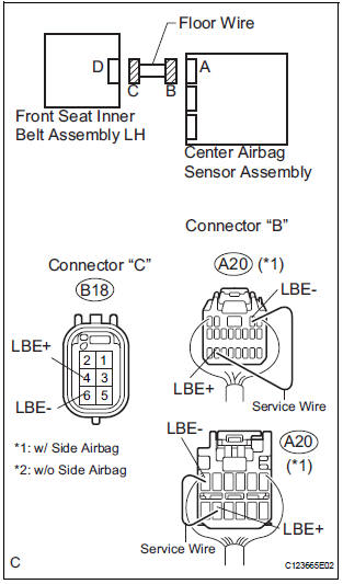
- Disconnect the connectors from the center airbag sensor assembly and the front seat inner belt assembly LH.
- w/ Side airbag: Using a service wire, connect A20-19 (LBE+) and A20-2 (LBE-) of connector "B".
NOTICE: Do not forcibly insert a service wire into the terminals of the connector when connecting.
- w/o Side airbag: Using a service wire, connect A20-11 (LBE+) and A20-6 (LBE-) of connector "B".
NOTICE: Do not forcibly insert a service wire into the terminals of the connector when connecting.
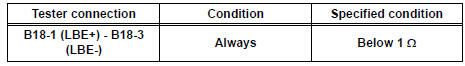
- Measure the resistance according to the value(s) in the table below.
Standard resistance
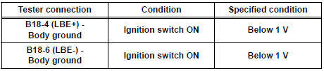
5 CHECK FLOOR WIRE (SHORT TO B+)
- Disconnect the service wire from connector "B".
- Connect the negative (-) terminal cable to the battery, and wait for at least 2 seconds.
- Turn the ignition switch to the ON position.
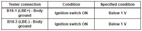
- Measure the voltage according to the value(s) in the table below.
Standard voltage
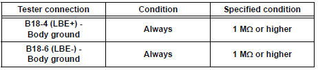
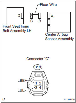
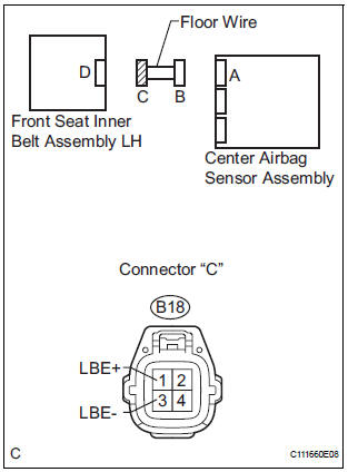
6 CHECK FLOOR WIRE (SHORT TO GROUND)
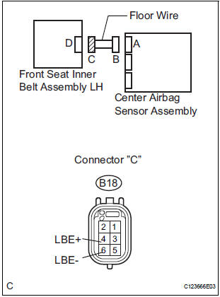
- Turn the ignition switch to the LOCK position.
- Disconnect the negative (-) terminal cable from the battery, and wait for at least 90 seconds.
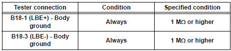
- Measure the resistance according to the value(s) in the table below.
Standard resistance
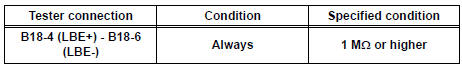
7 CHECK FLOOR WIRE (SHORT)
- Measure the voltage according to the value(s) in the table below.
Standard resistance
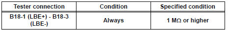
8 CHECK FRONT SEAT INNER BELT ASSEMBLY LH
- Connect the connectors to the front seat inner belt assembly LH and the center airbag sensor assembly.
- Connect the negative (-) terminal cable to the battery, and wait for at least 2 seconds.
- Turn the ignition switch to the ON position, and wait for at least 60 seconds.
- Clear the DTCs stored in memory.
- Turn the ignition switch to the LOCK position.
- Turn the ignition switch to the ON position, and wait for at least 60 seconds.
- Check the DTCs.
OK: DTC B0126/27 is not output.
HINT: Codes other than code B0126/27 may be output at this time, but they are not related to this check.
USE SIMULATION METHOD TO CHECK
9 REPLACE FRONT SEAT INNER BELT ASSEMBLY LH
- Turn the ignition switch to the LOCK position.
- Disconnect the negative (-) terminal cable from the battery, and wait for at least 90 seconds.
- Replace the front seat inner belt assembly LH.
HINT: Perform the inspection using parts from a normal vehicle if possible.
10 CHECK CENTER AIRBAG SENSOR ASSEMBLY
- Connect the negative (-) terminal cable to the battery, and wait for at least 2 seconds.
- Turn the ignition switch to the ON position, and wait for at least 60 seconds.
- Clear the DTCs stored in memory.
- Turn the ignition switch to the LOCK position.
- Turn the ignition switch to the ON position, and wait for at least 60 seconds.
- Check the DTCs.
OK: DTC B0126/27 is output.
HINT: Codes other than code B0126/27 may be output at this time, but they are not related to this check.
END
11 CHECK FLOOR WIRE (OPEN)
- Disconnect the connectors from the center airbag sensor assembly and the front seat inner belt assembly LH.
- w/ Side airbag:
Using a service wire, connect A20-19 (LBE+) and A20-2
(LBE-) of connector "B".
NOTICE: Do not forcibly insert a service wire into the terminals of the connector when connecting.
- w/o Side airbag:
Using a service wire, connect A20-11 (LBE+) and A20-6
(LBE-) of connector "B".
NOTICE: Do not forcibly insert a service wire into the terminals of the connector when connecting.
- Measure the resistance according to the value(s) in the table below.
Standard resistance
12 CHECK FLOOR WIRE (SHORT TO B+)
- Disconnect the service wire from connector "B".
- Connect the negative (-) terminal cable to the battery, and wait for at least 2 seconds.
- Turn the ignition switch to the ON position.
- Measure the voltage according to the value(s) in the table below.
Standard voltage
13 CHECK FLOOR WIRE (SHORT TO GROUND)
- Turn the ignition switch to the LOCK position.
- Disconnect the negative (-) terminal cable from the battery, and wait for at least 90 seconds.
- Measure the resistance according to the value(s) in the table below.
Standard resistance
14 CHECK FLOOR WIRE (SHORT)
- Measure the resistance according to the value(s) in the table below.
Standard resistance
15 CHECK FRONT SEAT INNER BELT ASSEMBLY LH
- Connect the connectors to the front seat inner belt assembly LH and the center airbag sensor assembly.
- Connect the negative (-) terminal cable to the battery, and wait for at least 2 seconds.
- Turn the ignition switch to the ON position, and wait for at least 60 seconds.
- Clear the DTCs stored in memory.
- Turn the ignition switch to the LOCK position.
- Turn the ignition switch to the ON position, and wait for at least 60 seconds.
- Check the DTCs.
OK: DTC B0126/27 is not output.
HINT: Codes other than code B0126/27 may be output at this time, but they are not related to this check.
USE SIMULATION METHOD TO CHECK
16 REPLACE FRONT SEAT INNER BELT ASSEMBLY LH
- Turn the ignition switch to the LOCK position.
- Disconnect the negative (-) terminal cable from the battery, and wait for at least 90 seconds.
- Replace the front seat inner belt assembly LH.
HINT: Perform the inspection using parts from a normal vehicle if possible.
17 CHECK CENTER AIRBAG SENSOR ASSEMBLY
- Connect the negative (-) terminal cable to the battery, and wait for at least 2 seconds.
- Turn the ignition switch to the ON position, and wait for at least 60 seconds.
- Clear the DTCs stored in memory.
- Turn the ignition switch to the LOCK position.
- Turn the ignition switch to the ON position, and wait for at least 60 seconds.
- Check the DTCs.
OK: DTC B0126/27 is not output.
HINT: Codes other than code B0126/27 may be output at this time, but they are not related to this check.
END
 Short to B+ in Side Squib LH Circuit
DTC B0118/46 Short to B+ in Side Squib LH Circuit
DESCRIPTION
The side squib LH circuit consists of the center airbag sensor assembly and
the front seat side airbag
assembly LH (side squib LH).
...
 Short in Front Pretensioner Squib RH Circuit
DTC B0130/63 Short in Front Pretensioner Squib RH Circuit
DESCRIPTION
The front pretensioner squib RH circuit consists of the center airbag sensor
assembly and the front seat
outer belt assembly ...
Other materials:
Disassembly
1. REMOVE 2ND BRAKE PISTON RETURN SPRING
SUB-ASSEMBLY
(a) Place SST on the return spring and compress the
return spring with a press.
SST 09387-00060
(b) Using a screwdriver, remove the snap ring.
(c) Remove the 2nd brake piston return spring.
2. REMOVE 2ND BRAKE PISTON
(a) Hold ...
System Too Lean/ System Too Rich
DTC P0171 System Too Lean (Bank 1)
DTC P0172 System Too Rich (Bank 1)
DTC P0174 System Too Lean (Bank 2)
DTC P0175 System Too Rich (Bank 2)
DESCRIPTION
The fuel trim is related to the feedback compensation value, not to the basic
injection time. The fuel trim
consists of both the short-term ...
Disposal
HINT:
Use the same procedures for the RH side and LH side.
The procedures listed below are for the LH side.
When scrapping a vehicle equipped with the SRS or
disposing of the front seat side airbag assembly, be sure to
deploy the airbag first in accordance with the proc ...
