Toyota Sienna Service Manual: Short to B+ in CAN Bus Line
DESCRIPTION
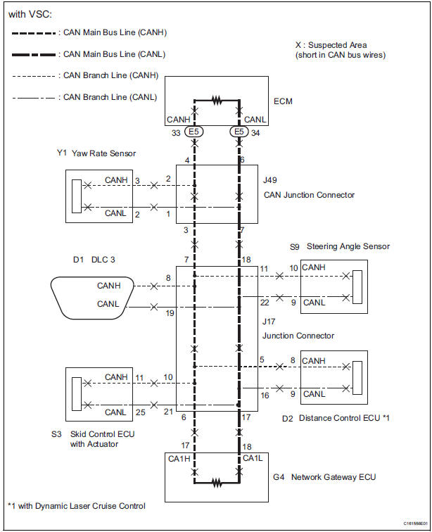
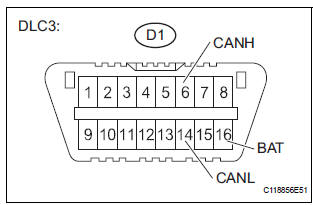
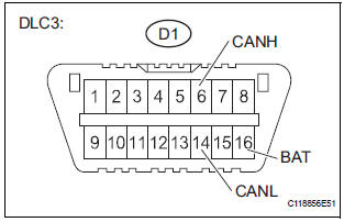
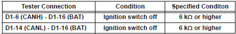
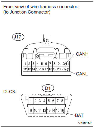
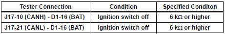
A short to B+ is suspected in the CAN bus wire when the resistance between terminals 6 (CANH) and 16 (BAT), or terminals 14 (CANL) and 16 (BAT) of the DLC3 is below 6 kΩ.
|
Symptom |
Trouble Area |
| The resistance between terminals 6 (CANH) and 16 (BAT), or terminals 14 (CANL) and 16 (BAT) of the DLC3 is below 6 kΩ. |
|
WIRING DIAGRAM

INSPECTION PROCEDURE
NOTICE:
- Turn the ignition switch off before measuring the resistances of CAN bus main wires and CAN bus branch wires.
- After the ignition switch is turned off, check that the key reminder warning system and light reminder warning system are not in operation.
- Before measuring the resistance, leave the vehicle as is for at least 1 minute and do not operate the ignition switch, any other switches, or the doors. If any doors need to be opened in order to check connectors, open the doors and leave them open.
HINT: Operating the ignition switch, any switches, or any doors triggers related ECU and sensor communication with the CAN. This communication will cause the resistance value to change.
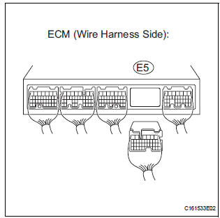
1 CHECK FOR SHORT TO B+ IN CAN BUS WIRE (ECM MAIN BUS WIRE)
- Turn the ignition switch off.
- Disconnect the ECM connector .
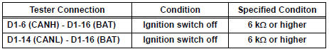
- Measure the resistance according to the value(s) in the table below.
Standard resistance
REPLACE ECM
2 CHECK FOR SHORT TO B+ IN CAN BUS WIRE (NETWORK GATEWAY MAIN BUS WIRE)
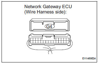
- Disconnect the Network gateway ECU connector .
- Measure the resistance according to the value(s) in the table below.
Standard resistance
REPLACE NETWORK GATEWAY ECU
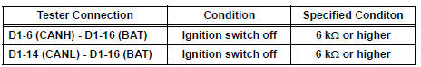
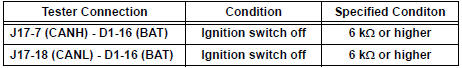
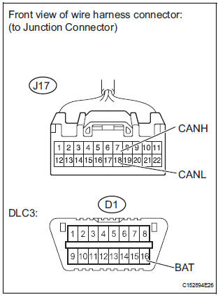
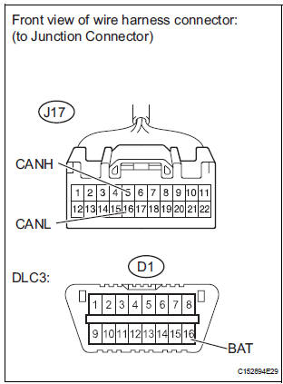
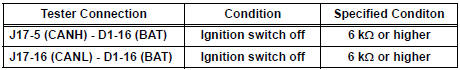
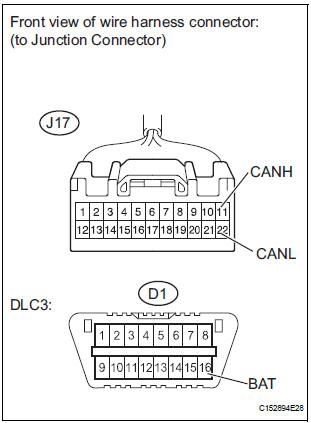
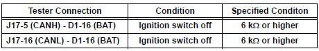
3 CHECK FOR SHORT TO B+ IN CAN BUS WIRE (DLC3 BRANCH WIRE)
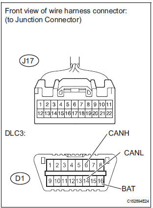
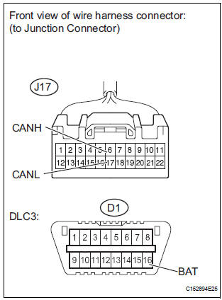
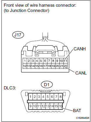
- Disconnect the junction connector (J17).
- Measure the resistance according to the value(s) in the table below.
Standard resistance
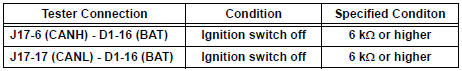
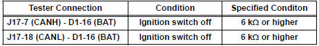
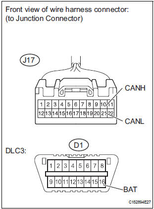
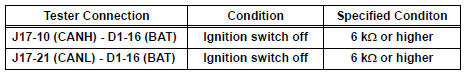
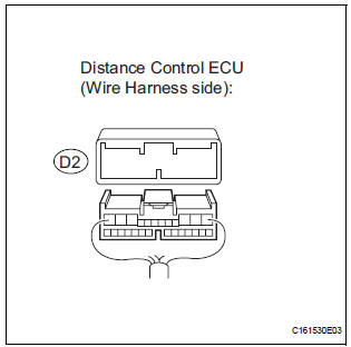
4 CHECK FOR SHORT TO B+ IN CAN BUS WIRE (JUNCTION CONNECTOR - NETWORK GATEWAY MAIN BUS WIRE)
- Measure the resistance according to the value(s) in the table below.
Standard resistance
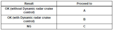
Result
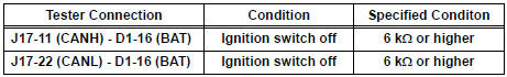
5 CHECK FOR SHORT TO B+ IN CAN BUS WIRE (JUNCTION CONNECTOR - ECM MAIN BUS WIRE)

- Measure the resistance according to the value(s) in the table below.
Standard resistance
REPLACE WIRING HARNESS CONNECTOR (JUNCTION CONNECTOR)
6 CHECK FOR SHORT TO B+ IN CAN BUS WIRE (JUNCTION CONNECTOR - CAN JUNCTION CONNECTOR MAIN BUS WIRE)
- Measure the resistance according to the value(s) in the table below.
Standard resistance
7 CHECK FOR SHORT TO B+ IN CAN BUS WIRE (SKID CONTROL ECU BRANCH WIRE)
- Measure the resistance according to the value(s) in the table below.
Standard resistance
8 CHECK FOR SHORT TO B+ IN CAN BUS WIRE (STEERING ANGLE SENSOR BRANCH WIRE)
- Measure the resistance according to the value(s) in the table below.
Standard resistance
Result
REPLACE WIRING HARNESS CONNECTOR (JUNCTION CONNECTOR)
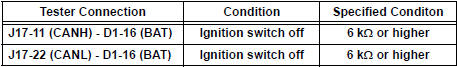
9 CHECK FOR SHORT TO B+ IN CAN BUS WIRE (DISTANCE CONTROL ECU BRANCH WIRE)
- Measure the resistance according to the value(s) in the table below.
Standard resistance
REPLACE WIRING HARNESS CONNECTOR (JUNCTION CONNECTOR)
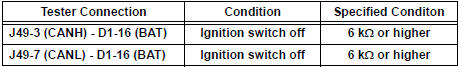
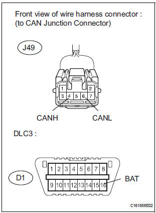
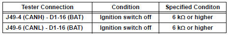
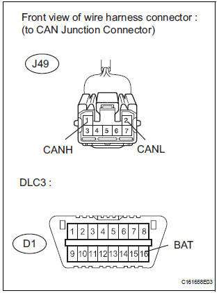
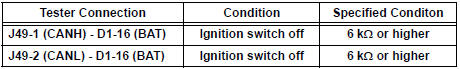
10 CHECK FOR SHORT TO B+ IN CAN BUS WIRE (CAN JUNCTION CONNECTOR - JUNCTION CONNECTOR MAIN BUS WIRE)
- Disconnect the junction connector (J49).
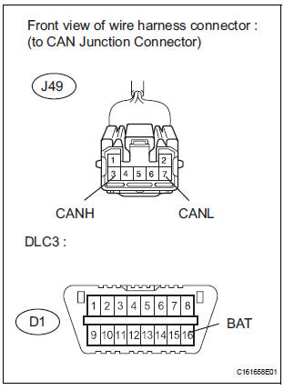
- Measure the resistance according to the value(s) in the table below.
Standard resistance
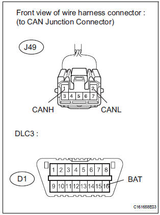
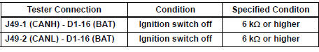
11 CHECK FOR SHORT TO B+ IN CAN BUS WIRE (CAN JUNCTION CONNECTOR - ECM MAIN BUS WIRE)
- Measure the resistance according to the value(s) in the table below.
Standard resistance
12 CHECK FOR SHORT TO B+ IN CAN BUS WIRE (YAW RATE SENSOR BRANCH WIRE)
- Measure the resistance according to the value(s) in the table below.
Standard resistance
REPLACE WIRING HARNESS CONNECTOR (CAN JUNCTION CONNECTOR)
13 CHECK FOR SHORT TO B+ IN CAN BUS WIRE (SKID CONTROL ECU BRANCH WIRE)
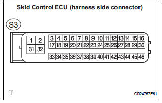
- Disconnect the skid control ECU connector.
- Measure the resistance according to the value(s) in the table below.
Standard resistance
REPLACE ABS & TRACTION ACTUATOR ASSEMBLY
14 CHECK CHECK FOR TO B+ IN BUS WIRE (STEERING ANGLE SENSOR BRANCH WIRE)
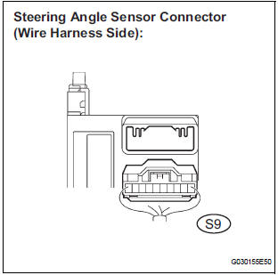
- Disconnect the steering angle sensor connector
- Measure the resistance according to the value(s) in the table below.
Standard resistance
REPLACE STEERING ANGLE SENSOR
15 CHECK CHECK FOR TO B+ IN BUS WIRE (DISTANCE CONTROL ECU BRANCH WIRE)
- Disconnect the distance control ECU connector.
- Measure the resistance according to the value(s) in the table below.
Standard resistance
16 CHECK CHECK FOR TO B+ IN BUS WIRE (YAW RATE SENSOR BRANCH WIRE)
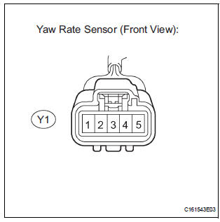
- Disconnect the yaw rate sensor connector
- Measure the resistance according to the value(s) in the table below.
Standard resistance
REPLACE YAW RATE SENSOR
 Short in CAN Bus Lines
DESCRIPTION
The CAN bus wires are considered to be shorted when the resistance between
terminals 6 (CANH) and
14 (CANL) of the DLC3 is below 54 Ω.
Symptom
Trouble Area
...
 Short to GND in CAN Bus Line
DESCRIPTION
A short to GND is suspected in the CAN bus wire when the resistance between
terminals 4 (CG) and 6
(CANH), or terminals 4 (CG) and 14 (CANL) of the DLC3 is below 200 Ω.
...
Other materials:
Rear Occupant Classification Sensor LH Circuit
Malfunction
DTC B1782 Rear Occupant Classification Sensor LH Circuit
Malfunction
DESCRIPTION
The rear occupant classification sensor LH circuit consists of the occupant
classification ECU and the rear
occupant classification sensor LH.
DTC B1782 is recorded when a malfunction is detected in the rear oc ...
Evaporator temperature sensor (for rear air conditioning system)
ON-VEHICLE INSPECTION
1. INSPECT REAR A/C EVAPORATOR TEMPERATURE SENSOR
(a) Remove the rear evaporator temperature sensor.
(b) Disconnect the connector from the rear evaporator
temperature sensor.
(c) Measure the resistance according to the value(s) in
the table below.
Standard re ...
Installation
1. INSTALL FOG LIGHT ASSEMBLY
Install the fog light assembly with the 2 claws and 2
pins.
2. INSTALL FRONT BUMPER ASSEMBLY
3. CONNECT CABLE TO NEGATIVE BATTERY
TERMINAL
4. VEHICLE PREPARATION FOR FOG LIGHT AIMING
5. PREPARATION FOR FOG LIGHT AIMING
6. FOG LIGHT AIMING INSPECT ...
