Toyota Sienna Service Manual: Short in Curtain Shield Squib RH Circuit
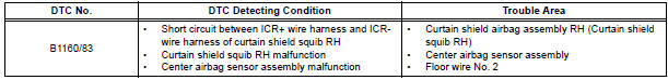
DTC B1160/83 Short in Curtain Shield Squib RH Circuit
DESCRIPTION
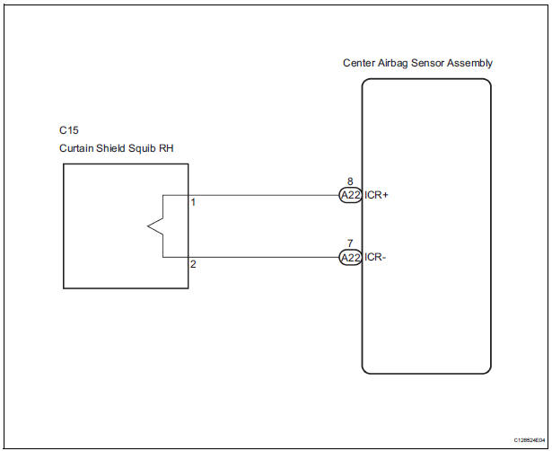
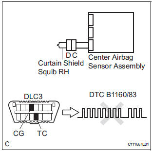
The curtain shield squib RH circuit consists of the center airbag sensor assembly and the curtain shield airbag assembly RH.
The circuit instructs the SRS to deploy when deployment conditions are met.
DTC B1160/83 is recorded when a short circuit is detected in the curtain shield squib RH circuit.
WIRING DIAGRAM
INSPECTION PROCEDURE
HINT:
- Perform the simulation method by selecting the "check mode" (signal check) with the intelligent test.
- After selecting the "check mode" (signal check), perform the simulation method by wiggling each connector of the airbag system or driving the vehicle on a city or rough road
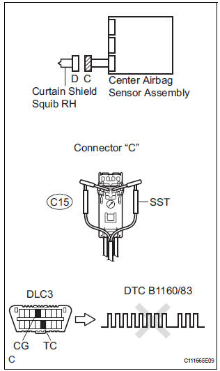
1 CHECK CURTAIN SHIELD AIRBAG ASSEMBLY RH (CURTAIN SHIELD SQUIB RH)
- Turn the ignition switch to the LOCK position.
- Disconnect the negative (-) terminal cable from the battery, and wait for at least 90 seconds.
- Disconnect the connectors from the curtain shield airbag assembly RH.
- Connect the white wire side of SST (resistance 2.1 Ω) to
the floor wire No. 2.
CAUTION: Never connect a tester to the curtain shield airbag assembly RH (Curtain shield squib RH) for measurement, as this may lead to a serious injury due to airbag deployment.
NOTICE: Do not forcibly insert the SST into the terminals of the connector when connecting.
Insert the SST straight into the terminals of the connector.
SST 09843-18060
- Connect the negative (-) terminal cable to the battery, and wait for at least 2 seconds.
- Turn the ignition switch to the ON position, and wait for at least 60 seconds.
- Clear the DTCs stored in memory.
- Turn the ignition switch to the LOCK position.
- Turn the ignition switch to the ON position, and wait for at least 60 seconds.
- Check the DTCs.
OK: DTC B1160/83 is not output.
HINT: Codes other than DTC B1160/83 may be output at this time, but they are not related to this check.
REPLACE CURTAIN SHIELD AIRBAG ASSEMBLY RH
2 CHECK CONNECTORS
- Turn the ignition switch to the LOCK position.
- Disconnect the negative (-) terminal cable from the battery, and wait for at least 90 seconds.
- Disconnect the SST (resistance 2.1 Ω) from the floor wire No. 2.
- Check that the floor wire No. 2 connectors (on the curtain shield airbag assembly RH side) are not damaged.
OK: The lock button is not disengaged, and the claw of the lock is not deformed or damaged.
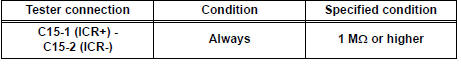
3 CHECK FLOOR WIRE NO.2 (CURTAIN SHIELD SQUIB RH CIRCUIT)
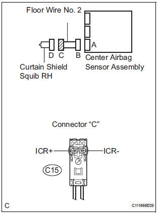
- Disconnect the connector from the center airbag sensor assembly.
- Release the activation prevention mechanism built into connector "B".
- Measure the resistance according to the value(s) in the table below.
Standard resistance
4 CHECK CENTER AIRBAG SENSOR ASSEMBLY
- Connect the connectors to the curtain shield airbag assembly RH and the center airbag sensor assembly.
- Connect the negative (-) terminal cable to the battery, and wait for at least 2 seconds.
- Turn the ignition switch to the ON position, and wait for at least 60 seconds.
- Clear the DTCs stored in memory.
- Turn the ignition switch to the LOCK position.
- Turn the ignition switch to the ON position, and wait for at least 60 seconds.
- Check the DTCs.
OK: DTC B1160/83 is not output.
HINT: Codes other than DTC B1160/83 may be output at this time, but they are not related to this check.
USE SIMULATION METHOD TO CHECK
 Rear Airbag Sensor LH Circuit Malfunction
DTC B1155/39 Rear Airbag Sensor LH Circuit Malfunction
DESCRIPTION
The rear airbag sensor LH circuit consists of the center airbag sensor
assembly and rear airbag sensor
LH.
If the center airb ...
 Open in Curtain Shield Squib RH Circuit
DTC B1161/84 Open in Curtain Shield Squib RH Circuit
DESCRIPTION
The curtain shield squib RH circuit consists of the center airbag sensor
assembly and the curtain shield
airbag assembly RH.
Th ...
Other materials:
Setting up intuitive parking assist
You can change the buzzer sound volume and the screen operating
conditions.
Press the “APPS” button.
Select “Setup” on the screen.
Select “Vehicle” on the screen.
Select “TOYOTA Park Assist Settings” on the screen.
Select the desired item.
The buzzer sound volu ...
Headlight dimmer switch
COMPONENTS
REMOVAL
1. REMOVE STEERING COLUMN LOWER COVER
2. REMOVE STEERING COLUMN UPPER COVER
3. REMOVE HEADLIGHT DIMMER SWITCH ASSEMBLY
Disconnect the connector.
Release the claw fitting and remove the headlight
dimmer switch assembly.
INSPECTION
1. HEADLIGHT DI ...
Diagnosis system
1. CHECK DLC3
The ECU uses ISO 15765-4 for communication.
The terminal arrangement of the DLC3 complies
with SAE J1962 and meets the ISO 15765-4 format.
NOTICE:
*: Before measuring the resistance, leave the
vehicle as is for at least 1 minute and do not
operate the igniti ...
