Toyota Sienna Service Manual: Open in Curtain Shield Squib RH Circuit
DTC B1161/84 Open in Curtain Shield Squib RH Circuit
DESCRIPTION
The curtain shield squib RH circuit consists of the center airbag sensor assembly and the curtain shield airbag assembly RH.
The circuit instructs the SRS to deploy when deployment conditions are met.
DTC B1161/84 is recorded when an open circuit is detected in the curtain shield squib RH circuit
WIRING DIAGRAM
INSPECTION PROCEDURE
HINT:
- Perform the simulation method by selecting the "check mode" (signal check) with the intelligent tester.
- After selecting the "check mode" (signal check), perform the simulation method by wiggling each connector of the airbag system or driving the vehicle on a city or rough road
1 CHECK CURTAIN SHIELD AIRBAG ASSEMBLY RH (CURTAIN SHIELD SQUIB RH)
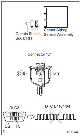
- Turn the ignition switch to the LOCK position.
- Disconnect the negative (-) terminal cable from the battery, and wait for at least 90 seconds.
- Disconnect the connectors from the curtain shield airbag assembly RH.
- Connect the white wire side of SST (resistance 2.1 Ω) to
the floor wire No. 2.
CAUTION: Never connect a tester to the curtain shield airbag assembly RH (Curtain shield squib RH) for measurement, as this may lead to a serious injury due to airbag deployment.
NOTICE: Do not forcibly insert the SST into the terminals of the connector when connecting.
Insert the SST straight into the terminals of the connector.
SST 09843-18060
- Connect the negative (-) terminal cable to the battery, and wait for at least 2 seconds.
- Turn the ignition switch to the ON position, and wait for at least 60 seconds.
- Clear the DTCs stored in memory.
- Turn the ignition switch to the LOCK position.
- Turn the ignition switch to the ON position, and wait for at least 60 seconds.
- Check the DTCs
OK: DTC B1161/84 is not output.
HINT: Codes other than DTC B1161/84 may be output at this time, but they are not related to this check.
REPLACE CURTAIN SHIELD AIRBAG ASSEMBLY RH
2 CHECK FLOOR WIRE NO.2 (CURTAIN SHIELD SQUIB RH CIRCUIT)
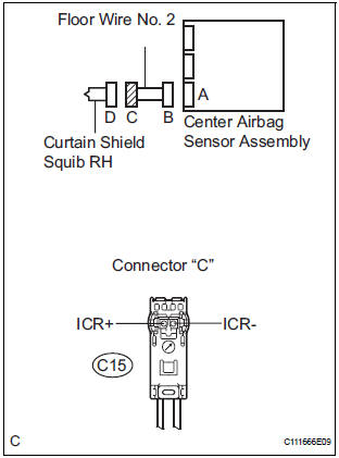
- Turn the ignition switch to the LOCK position.
- Disconnect the negative (-) terminal cable from the battery, and wait for at least 90 seconds.
- Disconnect the SST (resistance 2.1 Ω) from the floor wire No. 2.
- Disconnect the connector from the center airbag sensor assembly.
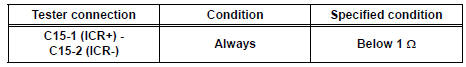
- Measure the resistance according to the value(s) in the table below.
Standard resistance
3 CHECK CENTER AIRBAG SENSOR ASSEMBLY
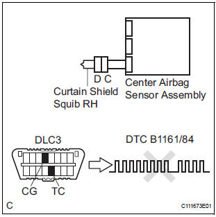
- Connect the connectors to the curtain shield airbag assembly RH and the center airbag sensor assembly.
- Connect the negative (-) terminal cable to the battery, and wait for at least 2 seconds
- Turn the ignition switch to the ON position, and wait for at least 60 seconds.
- Clear the DTCs stored in memory.
- Turn the ignition switch to the LOCK position.
- Turn the ignition switch to the ON position, and wait for at least 60 seconds.
- Check the DTCs.
OK: DTC B1161/84 is not output.
HINT: Codes other than DTC B1161/84 may be output at this time, but they are not related to this check.
USE SIMULATION METHOD TO CHECK
 Short in Curtain Shield Squib RH Circuit
DTC B1160/83 Short in Curtain Shield Squib RH Circuit
DESCRIPTION
The curtain shield squib RH circuit consists of the center airbag sensor
assembly and the curtain shield
airbag assembly RH.
T ...
 Short to GND in Curtain Shield Squib RH Circuit
DTC B1162/81 Short to GND in Curtain Shield Squib RH Circuit
DESCRIPTION
The curtain shield squib RH circuit consists of the center airbag sensor
assembly and the curtain shield
airbag assembly R ...
Other materials:
Removal
1. Remove rear wheel
2. Remove skid control sensor wire (for 2wd)
Hint:
(see page sp-38)
hint:
disconnect the rh side by the same procedures as the
lh side.
3. SEPARATE SPEED SENSOR REAR LH (for 4WD)
HINT:
(See page SP-38)
4. SEPARATE SPEED SENSOR REAR RH (for 4WD)
HINT:
Separate the RH ...
Installation
1. INSTALL TRANSFER RH BEARING RETAINER OIL SEAL
(a) Using SST, install a new transfer RH bearing
retainer oil seal to the transfer case at the position
as show in the illustration.
SST 09223-46011
NOTICE:
Do not install the oil seal obliquely
(b) Apply small amount of MP grease to the oi ...
MIL Circuit
DESCRIPTION
The MIL (Malfunction Indicator Lamp) is used to indicate vehicle malfunctions
detected by the ECM.
When the ignition switch is turned to the ON position, power is supplied to the
MIL circuit, and the ECM
provides the circuit ground which illuminates the MIL.
The MIL operation ...
