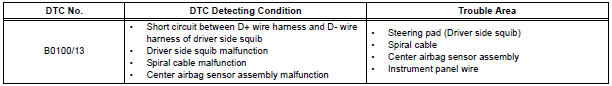
Toyota Sienna Service Manual: Short in Driver Side Squib Circuit
DTC B0100/13 Short in Driver Side Squib Circuit
DESCRIPTION
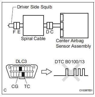
The driver side squib circuit consists of the center airbag sensor assembly, the spiral cable and the steering pad. The circuit instructs the SRS to deploy when deployment conditions are met. DTC B0100/13 is recorded when a short circuit is detected in the driver side squib circuit.
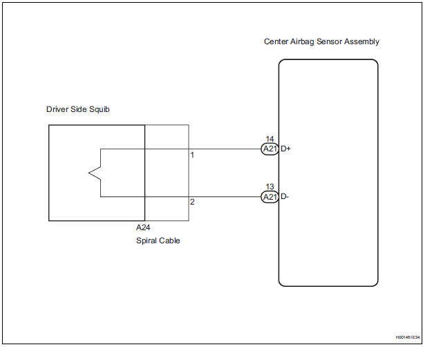
WIRING DIAGRAM
INSPECTION PROCEDURE
HINT:
- Perform the simulation method by selecting the "check mode" (signal check) with the intelligent tester
- After selecting the "check mode" (signal check), perform the simulation method by wiggling each connector of the airbag system or driving the vehicle on a city or rough road
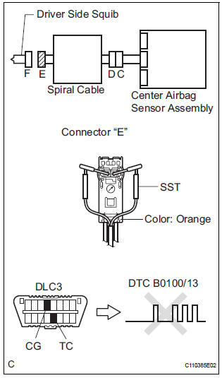
1 CHECK STEERING PAD (DRIVER SIDE SQUIB)
- Turn the ignition switch to the LOCK position.
- Disconnect the negative (-) terminal cable from the battery, and wait for at least 90 seconds.
- Disconnect the connectors from the steering pad.
- Connect the white wire side of SST (resistance 2.1 Ω) to the spiral cable.
CAUTION: Never connect a tester to the steering pad (driver side squib) for measurement, as this may lead to a serious injury due to airbag deployment.
NOTICE: Do not forcibly insert the SST into the terminals of the connector when connecting. Insert the SST straight into the terminals of the connector.
SST 09843-18060
- Connect the negative (-) terminal cable to the battery, and wait for at least 2 seconds.
- Turn the ignition switch to the ON position, and wait for at least 60 seconds.
- Clear the DTCs stored in memory.
- Turn the ignition switch to the LOCK position.
- Turn the ignition switch to the ON position, and wait for at least 60 seconds.
- Check the DTCs.
OK: DTC B0100/13 is not output.
HINT: Codes other than DTC B0100/13 may be output at this time, but they are not related to this check.
REPLACE STEERING PAD
2 CHECK CONNECTORS
- Turn the ignition switch to the LOCK position.
- Disconnect the negative (-) terminal cable from the battery, and wait for at least 90 seconds.
- Disconnect the SST (resistance 2.1 Ω) from the spiral cable.
- Check that the spiral cable connectors (on the steering pad side) are not damaged.
OK: The lock button is not disengaged, and the claw of the lock is not deformed or damaged.
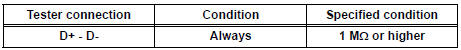
3 CHECK DRIVER SIDE SQUIB CIRCUIT
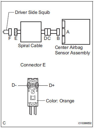
- Disconnect the connector from the center airbag sensor assembly.
- Release the activation prevention mechanism built into connector "B".
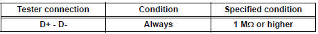
- Measure the resistance according to the value(s) in the table below.
Standard resistance
4 CHECK CENTER AIRBAG SENSOR ASSEMBLY
- Connect the connectors to the steering pad and the center airbag sensor assembly.
- Connect the negative (-) terminal cable to the battery, and wait for at least 2 seconds.
- Turn the ignition switch to the ON position, and wait for at least 60 seconds.
- Clear the DTCs stored in memory.
- Turn the ignition switch to the LOCK position.
- Turn the ignition switch to the ON position, and wait for at least 60 seconds.
- Check the DTCs.
OK: DTC B0100/13 is not output.
HINT: Codes other than code B0100/13 may be output at this time, but they are not related to this check.
USE SIMULATION METHOD TO CHECK
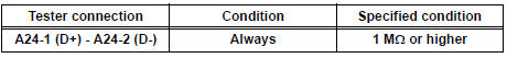
5 CHECK INSTRUMENT PANEL WIRE
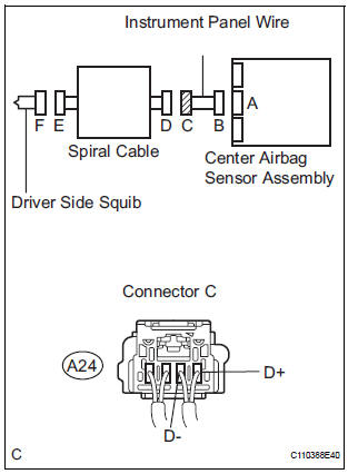
- Disconnect the instrument panel wire connector from the
spiral cable.
HINT: The activation prevention mechanism of connector "B" has already been released.
- Measure the resistance according to the value(s) in the table below.
Standard resistance
6 CHECK SPIRAL CABLE
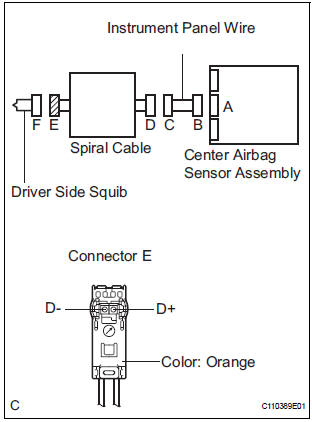
- Release the activation prevention mechanism built into connector "D".
- Measure the resistance according to the value(s) in the table below.
Standard resistance
USE SIMULATION METHOD TO CHECK
 Diagnostic trouble code chart
1. DTCS FOR AIRBAG SYSTEM
If a malfunction code is displayed during the DTC check,
check the circuit listed for the code in the table below
(Proceed to the page listed for that circuit).
HINT:
...
 Open in Driver Side Squib Circuit
DTC B0101/14 Open in Driver Side Squib Circuit
DESCRIPTION
The driver side squib circuit consists of the center airbag sensor assembly,
the spiral cable and the
steering pad.
The circuit instr ...
Other materials:
Installation
1. INSTALL CENTER AIRBAG SENSOR ASSEMBLY
Check that the ignition switch is off.
Check that the battery negative (-) terminal is
disconnected.
CAUTION:
After disconnecting the negative battery
terminal, wait for at least 90 seconds before
starting the operation.
&n ...
Installation
1. INSTALL SLIDE DOOR ROLLER ASSEMBLY UPPER
Apply MP grease to the rotating areas of the roller.
Install the roller with the 2 bolts.
Torque: 13 N*m (130 kgf*cm, 10 ft.*lbf)
2. INSTALL SLIDE DOOR HINGE ASSEMBLY CENTER LH
Apply MP grease to the rotating areas of the hinge.
In ...
Ambient temperature sensor
ON-VEHICLE INSPECTION
1. INSPECT A/C AMBIENT TEMPERATURE SENSOR
(a) Remove the A/C ambient temperature sensor.
(b) Disconnect the connector from A/C ambient
temperature sensor.
(c) Measure the resistance according to the value(s) in
the table below.
Standard resistance
NOTICE:
E ...
