Toyota Sienna Service Manual: Removal
NOTICE:
- Do not adjust the brake booster push rod.
- Do not change the combination of the diameter converting unit and brake.
1. REMOVE FRONT WHEEL
2. DRAIN BRAKE FLUID
NOTICE: Wash the brake fluid off immediately if it attaches to any painted surfaces.
3. SEPARATE BATTERY NEGATIVE TERMINAL
4. REMOVE FRONT DOOR SCUFF PLATE LH
5. REMOVE COWL SIDE TRIM BOARD LH
(a) Remove the nut and cowl trim board plate LH.
6. REMOVE INSTRUMENT PANEL FINISH PANEL SUBASSEMBLY LOWER LH
(a) Remove the 2 bolts and instrument panel finish panel sub-assembly lower LH.
7. REMOVE INSTRUMENT PANEL SAFETY PAD INSERT SUB-ASSEMBLY NO. 1
(a) Remove the 4 bolts and instrument panel safety pad insert sub-assembly No. 1.
8. REMOVE COWL TOP PANEL SUB-ASSEMBLY OUTER FRONT (See page SP-13)
9. REMOVE AIR CLEANER ASSEMBLY WITH HOSE
10. REMOVE BRAKE ACTUATOR ASSEMBLY (w/o VSC) SST 09023-00101
HINT: See page BC-184.
11. REMOVE ABS & TRACTION ACTUATOR ASSEMBLY (w/ VSC)
SST 09023-00101
HINT: See page BC-179.
12. REMOVE BRAKE LINE
(a) Remove the front brake tube No. 1, front brake tube No. 2, front brake tube No. 3 and front brake tube No. 4.
(b) Remove the rear brake tube No. 1 and rear brake tube No. 2.
13. REMOVE PUSH ROD PIN
(a) Remove the push rod pin from the brake booster push rod.
14. REMOVE BRAKE MASTER CYLINDER ASSEMBLY
(a) Slide the clip and disconnect the brake master cylinder reservoir hose from the brake master cylinder union.

(b) Slide the clip and disconnect the vacuum hose from the brake vacuum check valve assembly.
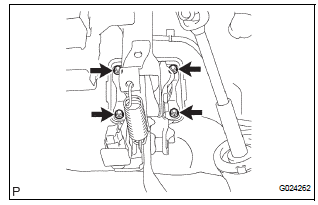
(c) Remove the 4 nuts and clevis.
(d) Pull out the brake booster with master cylinder.
15. REMOVE BRAKE BOOSTER GASKET
(a) Remove the brake booster gasket from the brake booster with master cylinder.
16. REMOVE BRAKE VACUUM CHECK VALVE ASSEMBLY
(a) Remove the brake vacuum check valve assembly and check valve grommet from the brake booster assembly.
 On-vehicle inspection
1. INSPECT BRAKE BOOSTER
(a) Air tightness check.
(1) Start the engine and stop it after 1 or 2 minutes.
Depress the brake pedal several times slowly.
HINT:
If the pedal goes down farthes ...
 Inspection
1. INSPECT BRAKE VACUUM CHECK VALVE ASSEMBLY
(a) Check the vacuum check valve.
(1) Slide the clip and disconnect the vacuum hose.
(2) Remove the vacuum check valve.
(3) Check that there ...
Other materials:
Installation
1. Install heated oxygen sensor (for bank 2
sensor 2) (see page ec-34)
2. Install front exhaust pipe assembly
(a) Install 2 new gaskets to the front exhaust pipe
assembly.
(b) Install the front exhaust pipe assembly with the 4
nuts.
Torque: 62 n*m (632 kgf*cm, 46 ft.*Lbf)
3. INSTALL CE ...
Unmatched Key Code
DTC B2795 Unmatched Key Code
DESCRIPTION
This DTC is output when a key with a code that has not been registered in the
ECU is inserted into the
ignition key cylinder.
DTC No.
DTC Detection Condition
Trouble Area
B2795
Key with unregistered key code is i ...
Identification information
VEHICLE IDENTIFICATION AND SERIAL NUMBERS
1. VEHICLE IDENTIFICATION NUMBER
(a) The vehicle identification number is stamped on the
vehicle identification number plate and the
certification label, as shown in the illustration.
A:
Vehicle Identification Number Plate
B:
...
