Toyota Sienna Service Manual: Short to B+ in Front Passenger Side Squib Circuit
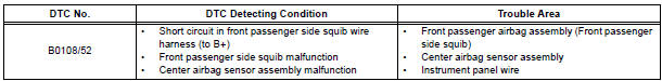
DTC B0108/52 Short to B+ in Front Passenger Side Squib Circuit
DESCRIPTION
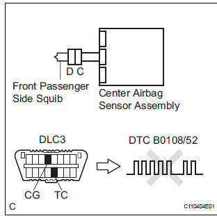
The front passenger side squib circuit consists of the center airbag sensor assembly and the front passenger airbag assembly.
The circuit instructs the SRS to deploy when deployment conditions are met.
DTC B0108/52 is recorded when a short to B+ is detected in the front passenger side squib circuit.
WIRING DIAGRAM
INSPECTION PROCEDURE
HINT:
- Perform the simulation method by selecting the "check mode" (signal check) with the intelligent tester.
- After selecting the "check mode" (signal check), perform the simulation method by wiggling each connector of the airbag system or driving the vehicle on a city or rough road
1 CHECK FRONT PASSENGER AIRBAG ASSEMBLY (FRONT PASSENGER SIDE SQUIB)
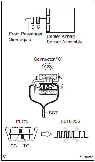
- Turn the ignition switch to the LOCK position.
- Disconnect the negative (-) terminal cable from the battery, and wait for at least 90 seconds.
- Disconnect the connectors from the front passenger airbag assembly.
- Connect the black wire side of SST (resistance 2.1 Ω) to the instrument panel wire.
CAUTION: Never connect a tester to the front passenger airbag assembly (front passenger side squib) for measurement, as this may lead to a serious injury due to airbag deployment.
NOTICE: Do not forcibly insert the SST into the terminals of the connector when connecting.
Insert the SST straight into the terminals of the connector.
SST 09843-18060
- Connect the negative (-) terminal cable to the battery, and wait for at least 2 seconds.
- Turn the ignition switch to the ON position, and wait for at least 60 seconds.
- Clear the DTCs stored in memory.
- Turn the ignition switch to the LOCK position.
- Turn the ignition switch to the ON position, and wait for at least 60 seconds.
- Check the DTCs.
OK: DTC B0108/52 is not output.
HINT: Codes other than DTC B0108/52 may be output at this time, but they are not related to this check.
REPLACE FRONT PASSENGER AIRBAG ASSEMBLY
2 CHECK INSTRUMENT PANEL WIRE (FRONT PASSENGER SIDE SQUIB CIRCUIT)
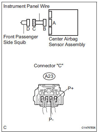
- Turn the ignition switch to the LOCK position.
- Disconnect the negative (-) terminal cable from the battery, and wait for at least 90 seconds.
- Disconnect the SST (resistance 2.1 Ω) from the instrument panel wire.
- Disconnect the connector from the center airbag sensor assembly.
- Connect the negative (-) terminal cable to the battery, and wait for at least 2 seconds.
- Turn the ignition switch to the ON position.
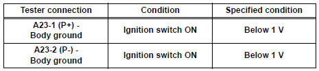
- Measure the voltage according to the value(s) in the table below.
Standard voltage
3 CHECK CENTER AIRBAG SENSOR ASSEMBLY
- Turn the ignition switch to the LOCK position.
- Disconnect the negative (-) terminal cable from the battery, and wait for at least 90 seconds.
- Connect the connectors to the front passenger airbag assembly and the center airbag sensor assembly.
- Connect the negative (-) terminal cable to the battery, and wait for at least 2 seconds.
- Turn the ignition switch to the ON position, and wait for at least 60 seconds.
- Clear the DTCs stored in memory.
- Turn the ignition switch to the LOCK position.
- Turn the ignition switch to the ON position, and wait for at least 60 seconds.
- Check the DTCs.
OK: DTC B0108/52 is not output.
HINT: Codes other than code B0108/52 may be output at this time, but they are not related to this check.
USE SIMULATION METHOD TO CHECK
 Short to GND in Front Passenger Side Squib
Circuit
Short to GND in Front Passenger Side Squib
Circuit
DTC B0107/51 Short to GND in Front Passenger Side Squib
Circuit
DESCRIPTION
The front passenger side squib circuit consists of the center airbag sensor
assembly and the front
passenger airbag as ...
 Short in Side Squib RH Circuit
DTC B0110/43 Short in Side Squib RH Circuit
DESCRIPTION
The side squib RH circuit consists of the center airbag sensor assembly and
the front seat side airbag
assembly RH.
The circuit instruct ...
Other materials:
Short in Front Pretensioner Squib LH Circuit
DTC B0135/73 Short in Front Pretensioner Squib LH Circuit
DESCRIPTION
The front pretensioner squib LH circuit consists of the center airbag sensor
assembly and the front seat
outer belt assembly LH.
This circuit instructs the SRS to deploy when deployment conditions are met.
DTC B0135/73 ...
Problem symptoms table
ENTIRE SYSTEM
METER GAUGES
WARNING LIGHTS
INDICATOR LIGHTS
BUZZER
ACCESSORY METER ASSEMBLY
...
Half Connection in Center Airbag Sensor
Assembly Connectors
DTC B1135/24 Half Connection in Center Airbag Sensor
Assembly Connectors
DESCRIPTION
The center airbag sensor assembly connector has a mechanism that electrically
detects half connection.
The center airbag sensor assembly monitors the voltage applied to the
disconnection detection pins and ...
