Toyota Sienna Service Manual: Tire Pressure Warning Reset Switch Circuit
DESCRIPTION
The ECU enters the initialization mode and performs initialization automatically, when the tire pressure warning ECU receives the signal from the tire pressure warning reset switch. If the ECU receives the signal, the tire pressure warning light blinks 3 times (1 second on, 1 second off).
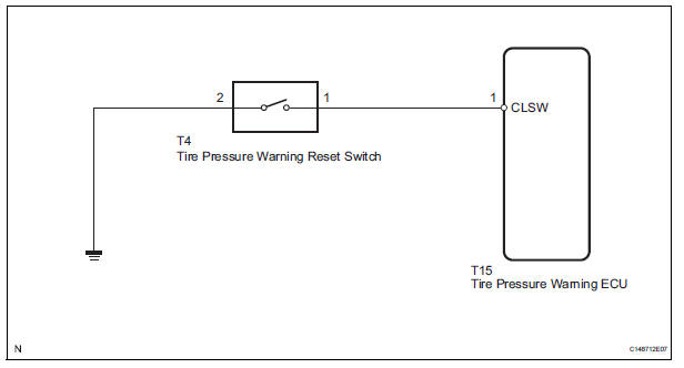
WIRING DIAGRAM
INSPECTION PROCEDURE
1 CHECK TIRE PRESSURE WARNING RESET SWITCH FUNCTION
(a) Perform the tire pressure warning reset switch test in TEST MODE PROCEDURE (See page TW-25).
OK: Reset switch ON: Tire pressure warning light comes on.
Reset switch OFF: Tire pressure warning light blinks.

END
2 INSPECT TIRE PRESSURE WARNING RESET SWITCH
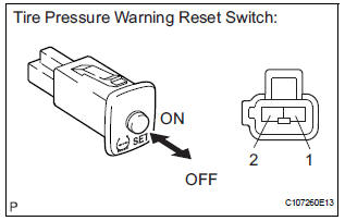
(a) Disconnect the tire pressure warning reset switch connector.
(b) Measure the resistance between terminals 1 and 2 of the tire pressure warning reset switch when the tire pressure warning switch is ON and OFF.
Standard resistance 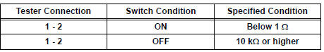

3 CHECK HARNESS AND CONNECTOR (TIRE PRESSURE WARNING RESET SW - TIRE PRESSURE WARNING ECU)
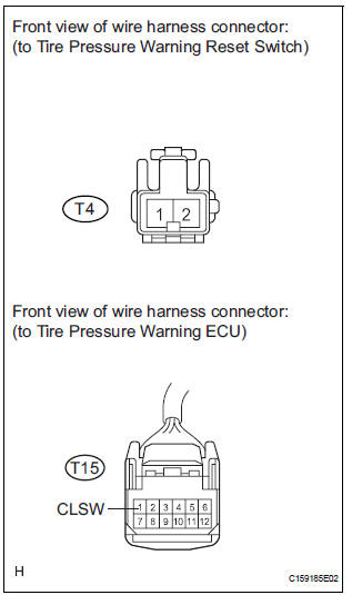
(a) Disconnect the tire pressure warning reset switch T4 connector and tire pressure warning ECU T15 connector.
(b) Measure the resistance according to the value(s) in the table below.
Standard resistance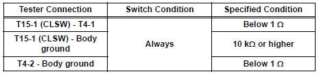

REPLACE TIRE PRESSURE WARNING ECU (See page TW-87)
 Vehicle Speed Signal Error (Test Mode DTC)
DTC C2191/91 Vehicle Speed Signal Error (Test Mode DTC)
DESCRIPTION
The tire pressure warning ECU receives a speed signal from the combination
meter. This DTC is stored
upon entering test mode, a ...
 Tire Pressure Warning Light Circuit
DESCRIPTION
If the ECU detects trouble, the tire pressure warning light blinks (comes on
after blinking for 1 minute) and
tire pressure monitor is cancelled at the same time. At this time, the ECU ...
Other materials:
Back-up Power Source Circuit
DESCRIPTION
This is the back-up power source for the A/C amplifier. Power is supplied
even when the ignition switch is
off and is used for diagnostic trouble code memory, etc.
WIRING DIAGRAM
INSPECTION PROCEDURE
1 INSPECT FUSE (ECU-B)
(a) Remove the ECU-B fuse from the engine room juncti ...
Installation
1. INSTALL POWER POINT SOCKET ASSEMBLY
Engage the 2 claws to install the power point socket
assembly.
2. INSTALL QUARTER TRIM FRONT PANEL ASSEMBLY
LH
3. INSTALL BACK DOOR SCUFF PLATE
4. INSTALL BACK DOOR WEATHERSTRIP
5. INSTALL REAR DOOR WEATHERSTRIP LH
6. INSTALL REAR DOOR S ...
Short to B+ in Curtain Shield Squib LH Circuit
DTC B1168/86 Short to B+ in Curtain Shield Squib LH Circuit
DESCRIPTION
The curtain shield squib LH circuit consists of the center airbag sensor
assembly and the curtain shield
airbag assembly LH.
The circuit instructs the SRS to deploy when deployment conditions are met.
DTC B1168/86 is ...
