Toyota Sienna Service Manual: Short to B+ in Rear Curtain Shield Squib RH Circuit
DTC B1633/82 Short to B+ in Rear Curtain Shield Squib RH Circuit
DESCRIPTION
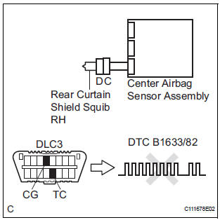
The rear curtain shield squib RH circuit consists of the center airbag sensor assembly and the curtain shield airbag assembly RH.
The circuit instructs the SRS to deploy when deployment conditions are met.
DTC B1633/82 is recorded when a short to B+ is detected in the rear curtain shield squib RH circuit.
WIRING DIAGRAM
INSPECTION PROCEDURE
HINT:
- Perform the simulation method by selecting the "check mode" (signal check) with the intelligent tester.
- After selecting the "check mode" (signal check), perform the simulation method by wiggling each connector of the airbag system or driving the vehicle on a city or rough road
1 CHECK CURTAIN SHIELD AIRBAG ASSEMBLY RH (REAR CURTAIN SHIELD SQUIB RH)
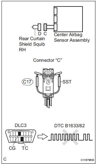
- Turn the ignition switch to the LOCK position.
- Disconnect the negative (-) terminal cable from the battery, and wait for at least 90 seconds.
- Disconnect the connectors from the curtain shield airbag assembly RH.
- Connect the white wire side of SST (resistance 2.1 Ω) to
the floor wire No. 2.
CAUTION: Never connect a tester to the curtain shield airbag assembly RH (Rear curtain shield squib RH) for measurement, as this may lead to a serious injury due to airbag deployment.
NOTICE: Do not forcibly insert the SST into the terminals of the connector when connecting.
Insert the SST straight into the terminals of the connector.
SST 09843-18060
- Connect the negative (-) terminal cable to the battery, and wait for at least 2 seconds.
- Turn the ignition switch to the ON position, and wait for at least 60 seconds.
- Clear the DTCs stored in memory.
- Turn the ignition switch to the LOCK position.
- Turn the ignition switch to the ON position, and wait for at least 60 seconds.
- Check the DTCs.
OK: DTC B1633/82 is not output.
HINT: Codes other than DTC B1633/82 may be output at this time, but they are not related to this check.
REPLACE CURTAIN SHIELD AIRBAG ASSEMBLY RH
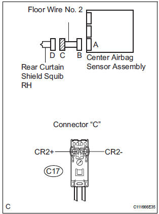
2 CHECK FLOOR WIRE NO.2 (REAR CURTAIN SHIELD SQUIB RH CIRCUIT)
- Turn the ignition switch to the LOCK position.
- Disconnect the negative (-) terminal cable from the battery, and wait for at least 90 seconds.
- Disconnect the SST (resistance 2.1 Ω) from the floor wire No. 2.
- Disconnect the connector from the center airbag sensor assembly.
- Connect the negative (-) terminal cable to the battery, and wait for at least 2 seconds.
- Turn the ignition switch to the ON position.
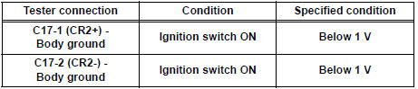
- Measure the voltage according to the value(s) in the table below.
Standard voltage
3 CHECK CENTER AIRBAG SENSOR ASSEMBLY
- Turn the ignition switch to the LOCK position.
- Disconnect the negative (-) terminal cable from the battery, and wait for at least 90 seconds.
- Connect the connectors to the curtain shield airbag assembly RH and the center airbag sensor assembly.
- Connect the negative (-) terminal cable to the battery, and wait for at least 2 seconds.
- Turn the ignition switch to the ON position, and wait for at least 60 seconds.
- Clear the DTCs stored in memory.
- Turn the ignition switch to the LOCK position.
- Turn the ignition switch to the ON position, and wait for at least 60 seconds.
- Check the DTCs.
OK: DTC B1633/82 is not output.
HINT: Codes other than code B1633/82 may be output at this time, but they are not related to this check.
USE SIMULATION METHOD TO CHECK
 Short to GND in Rear Curtain Shield Squib RH
Circuit
Short to GND in Rear Curtain Shield Squib RH
Circuit
DTC B1632/81 Short to GND in Rear Curtain Shield Squib RH
Circuit
DESCRIPTION
The rear curtain shield squib RH circuit consists of the center airbag sensor
assembly and the curtain
shield airbag ...
 Short in Rear Curtain Shield Squib LH Circuit
DTC B1635/87 Short in Rear Curtain Shield Squib LH Circuit
DESCRIPTION
The rear curtain shield squib LH circuit consists of the center airbag sensor
assembly and the curtain
shield airbag assembl ...
Other materials:
Distance Control ECU Power Source Circuit
DESCRIPTION
This circuit provides power to operate the distance control ECU. The distance
control ECU determines
information about the vehicle in front based on data from the laser sensor, and
then decides how much
acceleration and/or deceleration is needed to maintain the set distance. The
...
Repair
1. INTRODUCTION
(a) This section introduces ways to determine whether
the run-flat tire is repairable or not. Repair must be
performed by following the appropriate procedures.
If a flat tire occurs, it is possible to drive a maximum
of 160 km (100 miles) at a speed below 90 km/h (55
mph) due ...
Reassembly
1. INSTALL NO. 2 SEAT LEG SUB-ASSEMBLY
Install the No. 2 seat leg sub-assembly with the 3
bolts and nut.
Torque: 19 N*m (194 kgf*cm, 14 ft.*lbf)
NOTICE:
Tighten the bolts and nuts in the order shown in
the illustration.
Install the 3 clamps.
2. INSTALL NO. 2 SEAT ...
