Toyota Sienna Service Manual: Precaution
1. Check that the battery cables are connected to the correct terminals.
2. Disconnect the battery cables when the battery is given a quick charge.
3. Do not perform tests with a high voltage insulation resistance tester.
4. Never disconnect the battery cables while the engine is running.
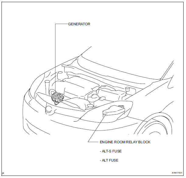
5. Check that the charging cable nut is tightened on terminal b of the generator and the engine room r/b.
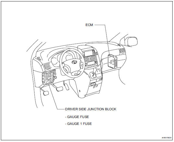
Parts location
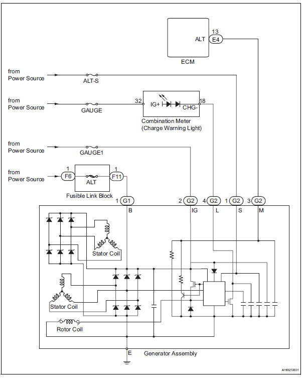
SYSTEM DIAGRAM
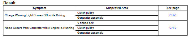
PROBLEM SYMPTOMS TABLE
 Charging system
...
 On-vehicle inspection
1. Check battery electrolyte level
(a) Check the electrolyte level.
(1) If the electrolyte level is low, replace the battery
(or add distilled water) and check the charging
system.
2. CHECK BAT ...
Other materials:
Radio and Navigation Assembly Communication Error
INSPECTION PROCEDURE
1 IDENTIFY THE COMPONENT SHOWN BY THE SUB-CODE
Enter the diagnostic mode.
Press the "LAN Mon" switch to change to "LAN Monitor"
mode.
Identify the component shown by the sub-code.
HINT:
"110 (multi-display)" i ...
Radio Receiver Communication Error
INSPECTION PROCEDURE
1 IDENTIFY THE COMPONENT SHOWN BY THE SUB-CODE
Enter the diagnostic mode
Press the preset switch "3" to change to "Detailed
Information Mode".
Identify the component shown by the sub-code.
HINT:
"190 (radio receiver) ...
Manual shifting test
1. Perform manual shifting test
Hint:
With this test, it can be determined whether the
trouble occurs in the electrical circuit or is a
mechanical problem in the transaxle.
If any abnormalities are found in the following test, the
problem is in the transaxle itself.
(A) disconnec ...
