Toyota Sienna Service Manual: Ignition Coil Primary / Secondary Circuit
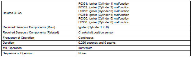
DTC P0351 Ignition Coil "A" Primary / Secondary Circuit
DTC P0352 Ignition Coil "B" Primary / Secondary Circuit
DTC P0353 Ignition Coil "C" Primary / Secondary Circuit
DTC P0354 Ignition Coil "D" Primary / Secondary Circuit
DTC P0355 Ignition Coil "E" Primary / Secondary Circuit
DTC P0356 Ignition Coil "F" Primary / Secondary Circuit
HINT:
- These DTCs indicate malfunctions relating to the primary circuit.
- If DTC P0351 is set, check the No. 1 ignition coil with igniter circuit.
- If DTC P0352 is set, check the No. 2 ignition coil with igniter circuit.
- If DTC P0353 is set, check the No. 3 ignition coil with igniter circuit.
- If DTC P0354 is set, check the No. 4 ignition coil with igniter circuit.
- If DTC P0355 is set, check the No. 5 ignition coil with igniter circuit.
- If DTC P0356 is set, check the No. 6 ignition coil with igniter circuit.
DESCRIPTION
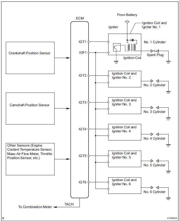
A Direct Ignition System (DIS) is used on this vehicle.
The DIS is a 1-cylinder ignition system in which each cylinder is ignited by one ignition coil and one spark plug is connected to the end of each secondary wiring. High-voltage is generated in the secondary wiring and then applied directly to each spark plug. The sparks of the spark plugs pass from the center electrodes to the ground electrodes.
The ECM determines the ignition timing and transmits the ignition (IGT) signals to each cylinder. Using the IGT signal, the ECM turns the power transistor inside the igniter on and off. The power transistor, in turn, switches on and off the current to the primary coil. When the current to the primary coil is cut off, highvoltage is generated in the secondary coil. This voltage is applied to the spark plugs, causing them to spark inside the cylinders. As the ECM cuts the current to the primary coil off, the igniter sends back an ignition confirmation (IGF) signal to the ECM, for each cylinder ignition.
|
DTC No. |
DTC Detection Condition |
Trouble Area |
|
P0351 |
No IGF signal to ECM while engine is running (1 trip detection logic) |
|
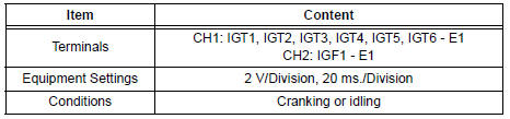
Reference: Inspection using an oscilloscope
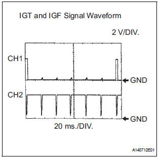
While cranking or idling, check the waveform between terminals IGT (1 to 6) and E1, and IGF1 and E1 of the ECM connector
MONITOR DESCRIPTION

If the ECM does not receive any IGF signals despite transmitting the IGT signal, it interprets this as a fault in the igniter and sets a DTC.
If the malfunction is not repaired successfully, a DTC is set 1 second after the engine is next started.
MONITOR STRATEGY
TYPICAL ENABLING CONDITIONS
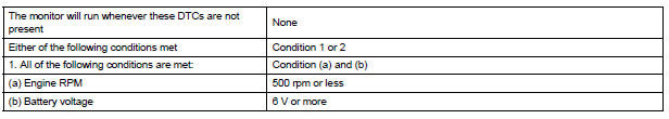

TYPICAL MALFUNCTION THRESHOLDS

COMPONENT OPERATING RANGE

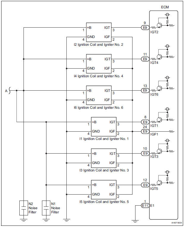
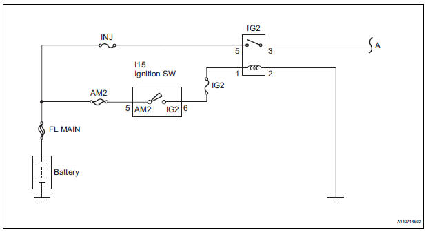
WIRING DIAGRAM
INSPECTION PROCEDURE
HINT: Read freeze frame data using the intelligent tester. The ECM records vehicle and driving condition information as freeze frame data the moment a DTC is stored. When troubleshooting, freeze frame data can be helpful in determining whether the vehicle was running or stopped, whether the engine was warmed up or not, whether the air-fuel ratio was lean or rich, as well as other data recorded at the time of a malfunction.
1 CHECK FOR SPARKS AND CHECK SPARK PLUG OF MISFIRING CYLINDER
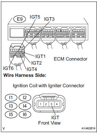
2 CHECK HARNESS AND CONNECTOR (IGNITION COIL ASSEMBLY - ECM (IGF1 SIGNAL TERMINAL))
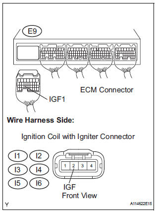
- Disconnect the I1, I2, I3, I4, I5 or I6 ignition coil with igniter connector.
- Disconnect the E9 ECM connector.
- Measure the resistance according to the value(s) in the table below.
Standard resistance: Check for open
Check for short
- Reconnect the ECM connector.
- Reconnect the ignition coil with igniter connector.
3 INSPECT ECM (IGF1 VOLTAGE)

- Disconnect the I1, I2, I3, I4, I5 or I6 ignition coil with igniter connector.
- Turn the ignition switch to the ON position.
- Measure the voltage according to the value(s) in the table below.
Standard voltage
- Reconnect the ignition coil connector
NG REPLACE ECM
REPLACE IGNITION COIL ASSEMBLY
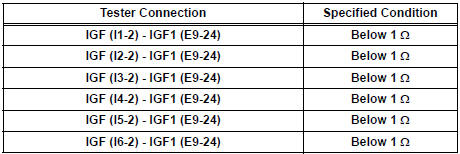
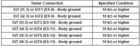
4 CHECK HARNESS AND CONNECTOR (IGNITION COIL ASSEMBLY - ECM (IGT SIGNAL TERMINAL))
- Disconnect the I1, I2, I3, I4, I5 or I6 ignition coil with igniter connector.
- Disconnect the E9 ECM connector.
- Measure the resistance according to the value(s) in the table below.
Standard resistance : Check for open
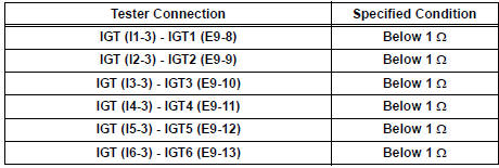
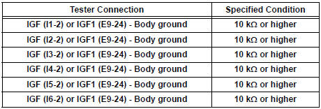
Check for short
NG REPAIR OR REPLACE HARNESS OR CONNECTOR (IGNITION COIL ASSEMBLY - ECM)
OK
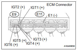
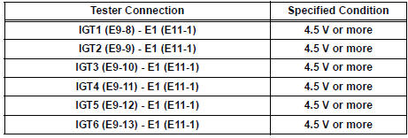
5 INSPECT ECM (IGT1, IGT2, IGT3, IGT4, IGT5 OR IGT6 VOLTAGE)
- Turn the ignition switch to the ON position.
- Measure the voltage according to the value(s) in the table below.
Standard voltage

NG REPLACE ECM
OK
6 INSPECT ECM (IGT1, IGT2, IGT3, IGT4, IGT5 OR IGT6 VOLTAGE)
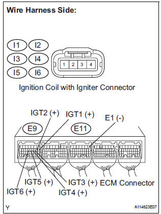
- Disconnect the I1, I2, I3, I4, I5 or I6 ignition coil connector.
- Turn the ignition switch to the ON position.
- Measure the voltage according to the value(s) in the table below.
Standard voltage
- Reconnect the ignition coil connector.
NG REPLACE ECM
OK
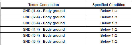
7 INSPECT IGNITION COIL ASSEMBLY (POWER SOURCE)
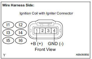
- Disconnect the I1, I2, I3, I4, I5 or I6 ignition coil with igniter connector.
- Measure the resistance according to the value(s) in the table below.
Standard resistance: Check for open
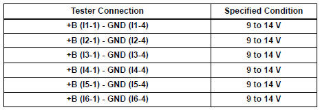
- Turn the ignition switch to the ON position.
- Measure the voltage according to the value(s) in the table below.
Standard voltage
- Reconnect the ignition coil with igniter connector.
NG Go to step 8
OK
REPLACE IGNITION COIL ASSEMBLY
8 INSPECT RELAY (IG2 RELAY)
- Remove the IG2 relay from the No. 3 engine room R/B.
- Measure the resistance according to the value(s) in the table below.
Standard resistance
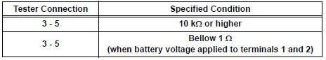
- Reinstall the IG2 relay.
NG REPLACE RELAY (IG2 RELAY)
OK
REPAIR OR REPLACE HARNESS OR CONNECTOR (IGNITION COIL ASSEMBLY - IGNITION SWITCH)
 Camshaft Position Sensor "A" Circuit
DTC P0340 Camshaft Position Sensor "A" Circuit (Bank 1
or Single Sensor)
DTC P0342 Camshaft Position Sensor "A" Circuit Low
Input (Bank 1 or Single Sensor)
DTC P0343 Camshaft P ...
 Camshaft Position Sensor
DTC P0365 Camshaft Position Sensor "B" Circuit (Bank 1)
DTC P0367 Camshaft Position Sensor "B" Circuit Low
Input (Bank 1)
DTC P0368 Camshaft Position Sensor "B" Circui ...
Other materials:
Removal
1. REMOVE V-BANK COVER SUB-ASSEMBLY (See
page EM-28)
2. REMOVE NO. 1 ENGINE UNDER COVER (See page
EM-26)
3. DRAIN ENGINE COOLANT (See page CO-6)
4. REMOVE NO. 2 AIR CLEANER INLET (See page EM-
28)
5. REMOVE BATTERY (See page EM-26)
6. REMOVE FRONT BUMPER ASSEMBLY (See page
ET-3)
7. REMOVE ...
Terminals of ECU
1. RADIO RECEIVER (10 SPEAKER SYSTEM)
*1: with Rear Seat Entertainment System
2. RADIO RECEIVER (6 SPEAKER SYSTEM)
*1: with Rear Seat Entertainment System
*2: without Rear Seat Entertainment System
3. STEREO COMPONENT AMPLIFIER
4. TELEVISION DISPLAY ASSEMBLY ...
On-vehicle inspection
1. INSPECT CURTAIN SHIELD AIRBAG ASSEMBLY
(VEHICLE NOT INVOLVED IN COLLISION)
Perform a diagnostic system check.
With the curtain shield airbag assembly installed on
the vehicle, perform a visual check. If there are any
defects as mentioned below, replace the front pillar
...
